Generally, street lights are switched on for whole night and during the day, they are switched off. But during the night time, street lights are not necessary if there is no traffic. Saving of this energy is very important factor these days as energy resources are getting reduced day by day.
Alternatives for natural resources are very less and our next generations may face lot of problems because of lack of these natural resources. We have already seen the circuit diagram and working of Auto Intensity Control of Street Lights circuit in the earlier post. This article describes about the circuit that switches the street lights on detecting vehicle movement and remains off after fixed time.
Street Lights that Glow on Detecting Vehicle Movement
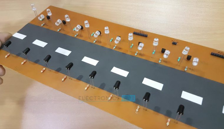
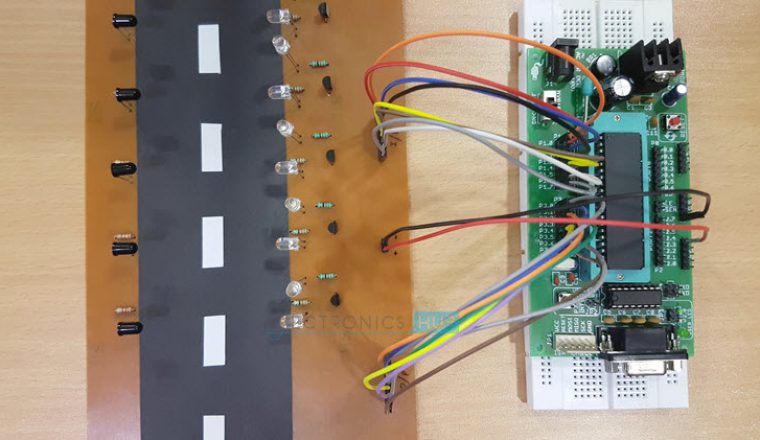
Construction and Output Video
Street Lights that Glow on Detecting Vehicle Movement (using AVR Microcontroller)
Principle Behind this Circuit
The proposed system consists of Atmega8 microcontroller, LDR, PIR sensor and RTC. This system controls the street lights using light dependent resistor and PIR sensor.
Street lights are switched on depending on the intensity of the Sun light on LDR. If the intensity of Sunlight on light dependent resistor is low, its resistance value is high. This value increases and becomes high when it is completely in dark. This resistance value decides when the street lights are required to switch ON.
As the resistance value is maximum in the midnights, real time clock comes into the play. The controller checks peak time during which there is no traffic and switch OFF the lights. When there is any vehicle on the road, it is detected by the PIR sensor.
Whenever PIR sensor is detected it just indicates the microcontroller to switch on the street lights. Then lights are switched on for 2 to 3 minutes and switched off automatically.
Another way to this approach is, one can maintain minimum intensity without completely switching off the lights by using PWM and switch them on to maximum intensity whenever it detects the vehicle. But in this article the circuit is designed in such a way that lights are completely switched OFF and will be switched ON only when there is any vehicle.
Circuit Diagram
Circuit Components
- ATmega8 microcontroller
- DS1307 IC
- PIR sensor
- LDR
- LCD
- LED array
Circuit Design
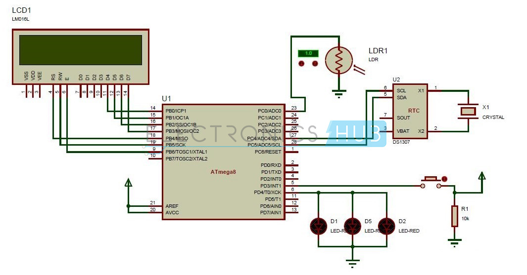
The proposed circuit consists of ATmega8 microcontroller, PIR sensor, light dependent resistor and real time clock, Liquid Crystal Display.
Passive Infrared sensor, also called as PIR sensor is connected to the PD0 pin of the microcontroller. PIR sensor senses the motion of the objects.
The PIR sensor internally will have an IR detector. Every object in the world radiates some IR rays. These are invisible to the human eye but electronic components can detect them. Different objects will emit IR rays of different wavelength. These rays were detected by the PIR sensor. PIR is initially high and is set to low automatically after sometime. Whenever it detects the motion of any object, it becomes low.
LDR is connected to the ADC pin – ADC0 of the microcontroller as LDR will produce analog value which is converted to digital by the ADC.
Light dependent resistors will have low resistance in light and high resistance in dark. The resistance of Light dependent resistor in dark is in range of ohms and in dark its resistance is in the range of mega ohms. When the light falls on LDR it resistance is reduced to a great extent.
Real time clock IC used is DS1307, which is I2C compatible. Real time clock has 8 pins.1 and 2 pins are connected to the crystal oscillator.3rd pin is connected to a battery.6th pin of RTC is connected to PC5 pin of microcontroller.5th pin is connected to PC4 pin of microcontroller.
I2C is inter integrated circuit. This is two wire interface protocol in which only two signals were used to transmit the data between two devices.
LCD is used for displaying time. LCD interfacing in 4bit mode is shown in the circuit diagram. Time from RTC is read and displayed on the LCD.
How to Operate this Circuit?
- Initially power the circuit.
- LCD displays the time read from RTC.
- Place the LDR in darkness. Now street light is switched ON.
- Now micro controller continuously checks the time. Street Light is switched on for fixed timings written in the code.
- After this time, they are switched of automatically.
- Place your hand in front of PIR sensor, this switches the street lights again, indicating that on the detection of any object street light is ON.
- After 2-3 seconds delay, lights are again switched of automatically.
Also Read the Related Post – Automatic Street Light Controller using Relays and LDR
Street Light That Glows on Detecting Vehicle Movement Using 8051 and IR sensor
The above circuit shows the street light that glows on detecting vehicle movement using avr. Here is the circuit that uses 8051 and IR sensors.
Circuit Diagram
Components
Microcontroller Section
-
-
- AT89C52 Microcontroller
- AT89C52 Programmer Board
- 11.0592 MHz Quartz Crystal
- 22pF Ceramic Capacitor
- 2 x 10K Resistor
- 10uF Electrolytic Capacitor
- Push Button
-
IR Transmitter and Receiver Section
-
-
- 8 x IR LED (IR Transmitters)
- 8 x 470R Resistor
- 8 x Photo Diode (IR Receivers)
- 8 x 3.3K Resistor
- 1K x 8 Resistor Pack
-
Load Section
-
-
- 8 x 2N2222 NPN Transistors
- 8 x 100R Resistor
- 8 x White LEDs
-
Principle of Operation
The principle behind the working of the project lies in the functioning of IR Sensor. We are going to use a Transmissive type IR Sensor in this project.
In Transmissive IR Sensor, the IR transmitter and receiver are placed facing each other so that IR receiver always detects IR Rays emitted by the IR Transmitter.
If there is an obstacle between the IR Transmitter and Receiver, the IR Rays are blocked by the obstacle and the IR Receiver stops detecting the IR Rays.
This can be configured to turn ON or OFF the LEDs (or street lights) with the help of microcontroller.

Circuit Design
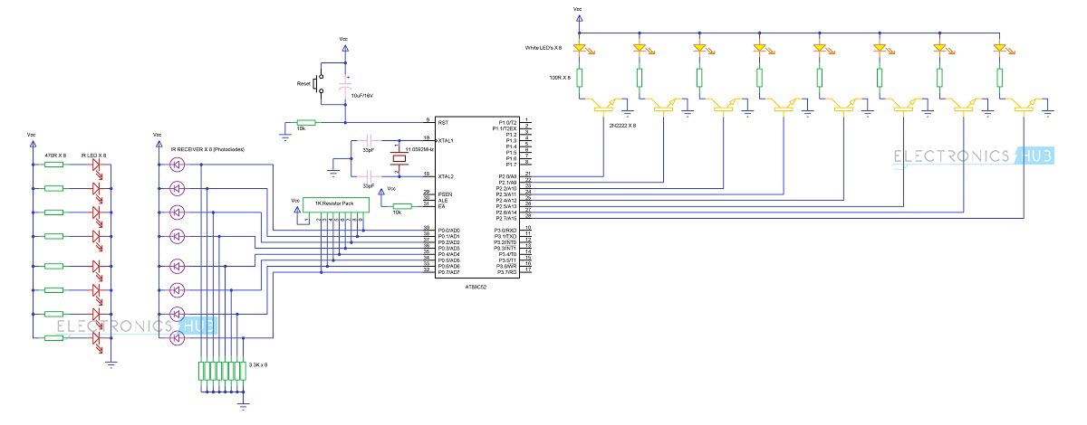
The main components of the project are AT89C52 Microcontroller, IR Sensor (IR Transmitter and IR Receiver) and LEDs.
The basic connections required for 8051 Microcontroller involve crystal, reset and External Access.
In order to use the on-chip oscillator, the 8051 microcontroller requires an external clock. This is provided by a crystal oscillator. An 11.0592MHz quartz crystal is connected to XTAL1 and XTAL2 pins with two 22pF ceramic capacitors connected to it.
The reset circuit of the microcontroller consists of a 10K resistor, 10uF capacitor and a push button. All the connections of the reset circuit are shown in the circuit diagram.
External access Pin is used to access external memory when it is connected to ground. Anyway, we are not going to use any external memory here. So, connect this pin to Vcc via a 10K resistor.
The next hard ware we are going to connect is the IR Receiver. We are going to connect the 8 IR receivers to port 0 pins of the microcontroller. In order to use the PORT0 as I/O port, we need to connect external pullup resistors to the port 0 pins.
After that, connect the output of the IR receiver i.e. anode terminal of the photo diode to port 0 pins. Cathode terminals of the photo diodes are connected to supply. Also, a 3.3k Resistor is connected between the anode terminal and ground.
The next part of the circuit is IR transmitter. IR transmitter is not a part of the microcontroller connections as the only job of the IR transmitter is to continuously emit infrared rays.
Hence, connect the 8 IR transmitters with corresponding 8 current limiting resistors of 470 ohms with a power supply.
Finally, we need to connect the LEDs. We need to connect the LED’s with the help of transistors to the PORT2 of the microcontroller. The base of the 8 2N2222 transistors is connected to the PORT 2 of the microcontroller while the emitters of the transistors are connected to ground.
An LED along with a series current limiting resistor of 100 ohms is connected to the each of the collector terminal of the transistor.
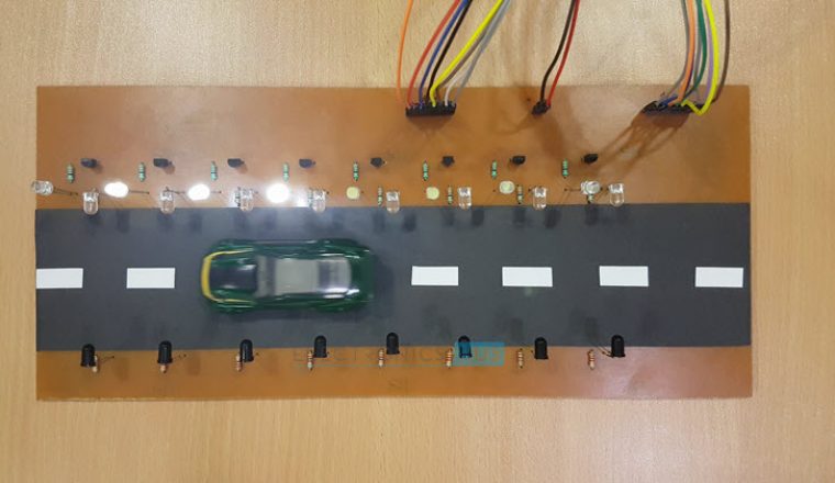
Working
The aim of this project is to design a street light control system using 8051 microcontroller, which automatically turns on or off the street lights by detecting the movement of vehicles. The working of the project is explained here.
Below GIF demonstrates the working of the project.
The IR transmitter is placed directly in line of sight with IR receiver, so that the IR receiver continuously receives infrared rays. Once the IR receiver receives infrared rays, the microcontroller will detect Logic 1. If the infrared rays are blocked by some means, the microcontroller will detect logic 0.
So, the program for the microcontroller must be written in such a way that it will turn ON the LEDs, which means here the street lamp, when it detects Logic 0 and it will turn OFF the LEDs, when it detects Logic 1.
Consider the two IR sensors i.e. IR Transmitter and IR Receiver are placed on the either side of the road. As per the circuit diagram, the IR receivers are connected to the PORT0 and the LEDs are connected to the PORT2 of the microcontroller.
At the beginning, when there is no obstacle, the IR receiver continuously detects IR light transmitted by the IR Transmitter. When a car or any other vehicle blocks any of the IR sensor, the microcontroller will turn ON the immediate three LEDs.
If the car blocks the first IR sensor, the first three LEDs are turned ON by the microcontroller. As the car moves forward and blocks the second IR sensor, the corresponding next three LEDs will be turned ON and the first LED of the previous set is turned OFF. The process continues this way for all the IR Sensors and LEDs.
Applications
- The street light control circuit can be used in normal roads, highways, express ways etc.
- The project can also be used in parking areas of malls, hotels, industrial lighting, etc.
Advantages
- If the lighting system implements all LED lights, the cost of the maintenance can be reduced as the life span and durability of LEDs is higher than Neon based lights which are normally used as street lights.
- As the lights are automatically turned ON or OFF, huge amount of energy can be saved.

91 Responses
good project which is very useful for the students
yes you are right this project is very useful in daily life and its very easy to operate
can you please send me the full details of the project
including the codes for further understanding
Program code of the project
led_nl1 bit p2.7
led_nl2 bit p2.4
led_nl3 bit p2.1
led_rd1s1 bit p2.0
led_rd2s1 bit p2.2
led_rd1s2 bit p2.3
led_rd2s2 bit p2.5
led_rd1s3 bit p2.6
led_rd2s3 bit p3.0
ip_ldr bit p1.0
ip_ir1 bit p1.1
ip_ir2 bit p1.2
ip_ir3 bit p1.3
cont1 equ 25h
cont2 equ 26h
cont3 equ 27h
cont4 equ 28h
org 0000h
ljmp main
org 0003h
reti
org 000bh
reti
org 0013h
reti
org 001bh
ljmp TIMER_1
reti
org 0023h
reti
TIMER_1:
clr tr1
mov tl1,#0b2h
mov th1,#03ah
mov a,cont1
inc a
cjne a,#20d,TIMER_NXT3
mov a,cont2
jz TIMER_NXT1
mov cont2,a
cjne a,#0d,TIMER_NXT1
TIMER_NXT1:
mov a,cont3
jz TIMER_NXT2
mov cont3,a
cjne a,#0d,TIMER_NXT2
setb led_rd1s2
setb led_rd2s2
TIMER_NXT2:
mov a,cont4
jz TIMER_NXT3
mov cont4,a
cjne a,#0d,TIMER_NXT3
setb led_rd1s3
setb led_rd2s3
TIMER_NXT3:
setb tr1
reti
main:
mov psw,#00h
mov sp,#70h
mov p0,#0ffh
mov p1,#0ffh
mov p2,#0ffh
mov p3,#0ffh
mov tmod,#10h
mov tcon,#00h
mov scon,#00h
mov tl1,#0b2h
mov th1,#03ah
mov ie,#88h
mov ip,#00h
setb led_nl1
setb led_nl2
setb led_nl3
setb led_rd1s1
setb led_rd2s1
setb led_rd1s2
setb led_rd2s2
setb led_rd1s3
setb led_rd2s3
mov cont1,#00h
mov cont2,#00h
mov cont3,#00h
mov cont4,#00h
setb tr1
main_lp:
jnb ip_ldr,nxt4
clr led_nl1
clr led_nl2
clr led_nl3
nxt1:
jb ip_ir1,nxt2
clr led_rd1s1
clr led_rd2s1
mov cont2,#05h
nxt2:
jb ip_ir2,nxt3
clr led_rd1s2
clr led_rd2s2
mov cont3,#05h
nxt3:
jb ip_ir3,nxt4
clr led_rd1s3
clr led_rd2s3
mov cont4,#02h
nxt4:
jnb ip_ldr,nxt5
setb led_nl1
setb led_nl2
setb led_nl3
setb led_rd1s1
setb led_rd2s1
setb led_rd1s2
setb led_rd2s2
setb led_rd1s3
setb led_rd2s3
nxt5:
ljmp main_lp
end
Is this code working perfectly
For which micro controller is this code
can anyone plz tell me that for which circuit diagram is this code working???
This code if for street light that glows on detecting vehicle movement using IR and 8051 microcontroller.
Bro error is coming can u please help or resend code
can u prepare this project????
can u please tell me the total cost of this project.
mail
Does climate such as fog, rain affects working of LDR? And whether the sensitivity of PIR is good? Please help me out
have a this project report
please provide the full details on the following projects:-
1.Street Lights that Glow on Detecting Vehicle Movement
2.IR Controlled Robotic Vehicle.
3.intelligent traffic light control and vechicle identification using traffic camers without ground sensor
4.desin of an intelligent electronic vechical for blind
Please send me the details of the project, including the source code.
sir, pls send me the source code for street light that glows on vehicle movement.
Please send microcontroller programing code please
can you please send me the full details of the project including the codes for further understanding
Can you please send me the full details of the project including the code for further understanding.
Greeeeeeeeeeeeeeeat
very nice project
nice project
Is this a acceptable project for IT ?????
yaaa… its a good idea to save the energy for our future use
very nice project
how much distance it will detect
It can detect upto 20feet
Hi anusha do you have full details of this project?
plz give me the code
Can you please provide me the code for this project..
please send me d project code i need it fr my openhouse project
did anyone of u got reply? plz send it to me too. i need it for my final year project.
send me the project code…i want to do this project fr openhouse expo
please send code for this project to my email address bcz i had open house expo
What are the softwares required in thiss..?
can u send me code of this project
can u send me full programming or code for project of automatic street light control…..please(( sunny9vk@gmail.com)) my id
plz give me the code of micro controller
Please send the source code of the project.
Please send me the source code for street light that glows on vehicle movement
i want to source code for Street Lights that Glow on Detecting Vehicle Movement Project argently can u send me this please…..
i want to source code for Street Lights that Glow on Detecting Vehicle Movement Project argently can u send me this please…..
Please send me the source code we want to implement this project
Please provide the source code of this project.
i am unable to find the code for this project. could you please help?
PLEASE SEND ME THE CODE TO THE PROJECT
can you pls provide the arduino coding for this?
Please send me the source code please. Need it for my project
Please send me the program file. Need it so bad
Please send the program code. Im currently doing school project. Please help me
Please send me the program code. Its for my school project
Please send me the coding. Need it for my EEE project
plz send me the code
Nice been light .
Pl project circuit layout hex file send me .all details waiting ur reply
Thanks
please send me the code its urgent
can u give me the source code and guidance to this project using arduino.
send me the code please
Very nice and useful project.
Please send me the details of the project, including the source code.
PLEASE SEND ME THE PCB LAYOUT & SOURCE CODE
can u give me the source code and guidance to this project using arduino
nice project,i like very much…
but can u give me detailed information including programme for controller.
Send me the code..!
nice project…can i get the coding
i wanna do this project for my final year project….and i need your help more about this project
Where can I get the source code ?
Can you guys send me the codes and full details of this project im going to use it in our house to save money and by the way nice project keep on sharing thanks. soranwindsor@gmail.com
Hello Sir , I will be very grateful of you if you kindly send me the full details of the project along with the programming ,
Nice project, where can I get the source code?
Nice project . Can I get the codes sir . I’ll be very grateful if you kindly send me the full details about this project so that I can get a better understanding
can you please send me full details of street lights that glow on vehicles movement including code for further understanding.
nice. can we implement same project using PSoC..???
Nice thought for the energy conservation…
Can u send me source for street light glows detecting vehicles using 8051
its a paid course …. is it secure to make payments ????
Yes it is a paid course..Yes it is secure..
Hello sir, may I have the source code of this project in C language?
Thanks in advance.
Can you send me report of this project, and codes , full details
Can i get code for this project plzz as soon as possible.
Can you share the code of Street Lights that Glow on Detecting Vehicle Movement using ATmega8?
My mail id is janvipatel4199@gmail.com.We want the code for reference of our project.
Sir can u please send me the code for microcontroller for the project Street Light That Glows on Detecting Vehicle Movement Using 8051 and IR sensor on harshalraut295@gmail.com
Overall good project but i want the cod so please can u give me that code ??
can u please send me the source code i.e the hex file for this project
please………..please…!!!
I have thes code it is working
#includereg51.h
#define stlight P2
#define sense P0
void main()
{
sense=0x0FF;
stlight=0x00;
while(1)
{
if (sense^0) if 1st ir is high
stlight=0x3; make 3 light on
if (sense^1) if 2nd ir is high
stlight=0x7; make 3 light on
if (sense^2) if 3rd ir is high
stlight=0x0e; make 3 light on
if (sense^3) if 4th ir is high
stlight=0x1C; make 3 light on
if (sense^4) if 5th ir is high
stlight=0x38; make 3 light on
if (sense^5) if 6th ir is high
stlight=0x70; make 3 light on
if (sense^6) if 7th ir is high
stlight=0xE0; make last 3 light on
if (sense^7) if 8th ir is high
stlight=0xC0; make last 2 light on
}
}
For which Microcontroller is this code used?
Can u please tell me how much distance required for PIR sensor to detect the vehicles?
The sensor we used can detect up to 10 meters at an angle +-15 degrees
we made this project and apply in one colony and it is working in very good manner
what is capacitor and resistor specifically used for here, could you please explain to me in details? and please what is the power supply in this circuit is it AC or DC and why? thanks..
can u plssss explain how to connect cicuit and the components required for it plsssssss
Can u tell me how to control the intensity of the light ….. because I don’t want to turn off the light…I want to decrease the intensity after the car passes…
how much space would the IR sensors take up and will they interfere with the Sight Distance?What are their dimensions
Can this project work for highway,where the speed of vehicles is greater than the normal roads also can their glow time be increased??