Did you ever think that how the street lights automatically turn ON in the night and turn OFF automatically at morning? Is there any person who comes to ON/OFF these lights? There are several ways to turn on the street lights but the following circuit describes an Automatic Street Light Controller Circuit that uses LDR and Relay to perform this job automatically.
The circuit employed here is an uncomplicated light/dark activated switch and contains a relay at its output, which simply turns ON/OFF a street light and further can be extended to control any electrical appliance in a household.
Related Post: Auto Intensity Control of Street Lights
Introduction
Many people have a phobia of darkness, so to assist them in such situations, we have explained a simple circuit that will automatically turn on the street light consisting of LEDs or bulb coupled with relay. It is lit well enough to see the objects nearby.
This circuit is very easy to work around and also it is battery operated. The power consumed by the circuit is very low because of the very few components used in the circuit.
The whole circuit is based on IC LM358, which is basically an operational amplifier that is configured in a voltage comparator. LDR (Light depending resistor), whose resistance is based upon the quantity of the light falling on it, is the main component for sensing the light. Along with these, a few more components are also used.
Circuit Diagram of Automatic Street Light Controller Switch Circuit

Components used in this Circuit
- IC LM358 – 1
- Resistor 10KΩ – 1
- Potentiometer 10KΩ – 1
- 5V Relay Module – 1
- Small LED Strip
- 9V Battery
- LDR – 1
- Connecting Wires
- Breadboard
Note: This circuit can also be built using microcontroller. To get an idea about the circuit built using microcontroller, read the post:Street Lights that Glow on Detecting Vehicle Movement.
Components Description
LM358
It is an Operational Amplifier IC. It is available ib 8-pin DIP Package and can be used in several configurations like Amplifier, oscillator, comparator etc.
LDR
LDR is a device whose sensitivity depends upon the intensity of light falling on it. When the strength of the light falling on LDR increases the LDR resistance decreases, while if the strength of the light falls on LDR is decreased, its resistance increased.
In the time of darkness or when there is no light, the resistance of LDR is in the range of mega ohms, while in the presence of light or in brightness in decrease by few hundred ohms.
Testing of LDR
Before mounting any component in the circuit it is a good practice to check whether a component works properly or not so that you can avoid consumption of time in troubleshooting. For testing LDR set the range of multimeter in resistance measurement.
Measure the resistance of LDR in the light or brightness and the resistance must be low. Now, cover the LDR properly so that no light falls on it and once again measure the resistance. It must be high. If you got the satisfactory result, then your LDR is good.
[Also Read: How To Make an Adjustable Timer ]
Resistor
It is a passive component having two terminals that is used to manage the current flow in the circuit. A current that flows via a resistor is directly proportional to the voltage that appears across the resistor.
Resistors are of two types –
i) Fixed Resistor – having a fixed value of resistance
ii) Variable Resistor – whose value of resistance can be changed for example if we have a resistor of 5K then the value of resistance will vary from 0 to 5 k.
Value of resistance can be calculated with the help of multimeter or with the color code that is visible on the resistor.
Relay
It provides isolation between the controller and the device because as we know devices may work on AC as well as on DC but they receive signals from microcontroller which works on DC hence we require a relay to bridge the gap. The relay is extremely useful when you need to control a large amount of current or voltage with the small electrical signal.
Factors for Selecting an appropriate Relay
- The voltage and current required to strengthen the coil.
- The maximum voltage which we will acquire in the output.
- Amount of the armature.
- Amount of contacts for the armature.
- Number of electrical associates (N/O and N/C).
NOTE: The Relay module used in this project is an active LOW Relay.
Automatic Street Light Controller Circuit Simulation Video (Old Circuit)
Working of Automatic Street Light Controller Switch Circuit
The working of circuit is very much easy to understand. In this circuit, we used IC LM358, which is basically an operational amplifier. Pins 2 and 3 of these IC are used to compare the voltage and give us an output as high or low depending on the voltages at the input pins.
In this circuit, LDR and 10KΩ Resistor form one potential divider pair, which is used to provide a variable voltage at the non-inverting input (that is Pin 3). The second potential divider is built around inverting input (Pin 2) with the help of 10KΩ Potentiometer, which will supply half of the supply voltage to inverting pin.
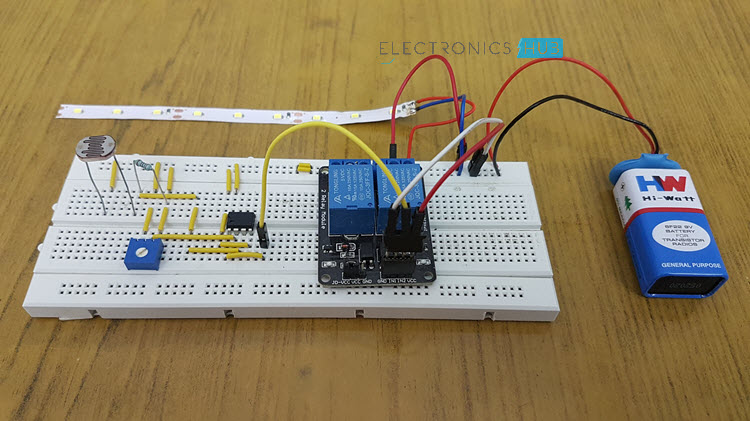
As we know the property of LDR that during the day time, its resistance is low, the voltage at the non-inverting input (i.e. pin 3) is higher than the voltage at the inverting input (pin 2). Hence, the output at the pin 1 is high. As a result, the relay is OFF and the LED (or the bulb) will not glow.
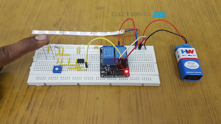
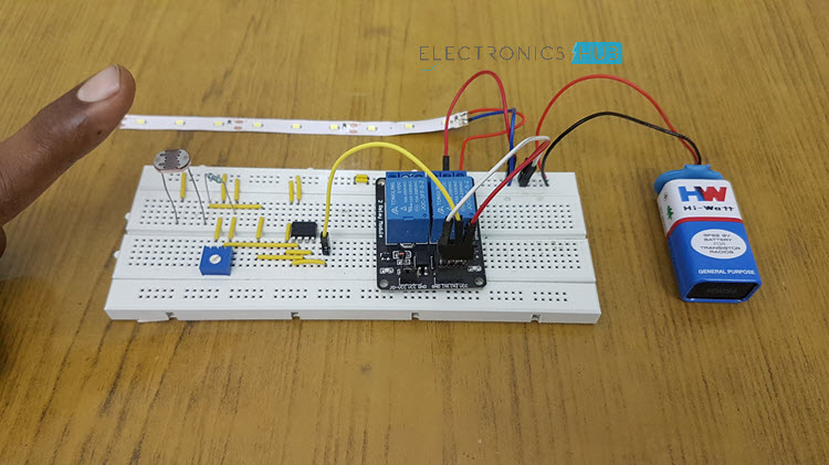
But in dimness or at night time, we know that resistance of LDR is high. Hence, the voltage at non-inverting input pin 3 of the IC LM358 decreases than the inverting input pin 2. As a result, the output pin 1 moves to low state, which further makes the relay to activate and the LED or bulb associated to it will glow.

44 Responses
Is it possible to use this setup without using a relay??
Yes. If you use LED’s you can
Can i still use 9 v battery to power the whole circuit using led
yes
you can use mosfet instead a relay
i want to know that to PCB of “Automatic Street Light Controller Circuit Using Relays and LDR” will how much cost.
its cheap now at radio shack, mind you radio shack is closing or out of business so grab the opportunity, every thing is 75 % off
Hello,
R2 is 560E. What is 560E ? is it 560 ohm ?
Best Regards
Beyazit.
Yes E is for ohm
can u send me exact bom for this project.
for 45 w led street lamp can u send me the circuit diagram ….please
sir can u pls provide the procedure for the connection of components on breadboard !!!!!
can i use 12 relay instead of 5 v
No 12v relay requires 12v to switch..
Could you please tell me the voltage and wattage rating of lamp used in this project!!!!!!
Will u pls send me the same circuit using 2 transistor with 2 LDR 555n timer with relay??
Can we use a sensor for detecting dark or bright.
Yes
Pls this automatic switch with relay, how do I power it? Because it is not indicated thanks
What is rating of relay. For example 100 to 500 watt lamp.
Hi,
By varying variable resistor, will I be able to control On and Off the light at required light intensity….how ??? Please explain…
can switch on and Off the light at my interested light intensity with this circuit…..please explain
Yes you can .by adjusting the variable resistor value
Can you please tell me the lamp you used in this project of howmany volts
which ldr having high sensitivity 12 mm or 5 mm or anything else
please reply.
at output side if I connect tube light anything will happen or its work?
Hello,
I have designed same circuit and it is working properly if power supply is on continuously, But when Relay is in ON condition and I Off and On the main power supply I cannot get relay in ON condition.
What is the solution?
Please give me its solution to solve this problem
can i get the abstract or report for the project automatic street light controller?
Can u give mi the exact value of LDR which was used in this project
What is the contribution of transistor and capacitor in this automatic street light controller circuit??
What can be the maximum range of infrared sensor available in present scenario
PlZ send the circuit diagram of automatic street light using transformer ,bridge ntransistor BC547, ldr , relay
please send me a diagram of a robot using magnetic contactors and timers
what type of ldr is used in this process
Can I use LM358 or comperator. If i can do that then how is it works
May I know why you use 8051 microcontrollers not PIC
Which software
Could you be more specific?
WHY CAPACITOR IS USED ..plz say the purpose of capacitor
Sir, how we will decide the values of resistors and capacitors? can you please give me a detail explanation.
I want the design of automatic Street light using ldr design which gives the requirement of each components values
Can i have whole circuit diagram along side with pdf plz
Would it be possible to set up 5 individual LEDs instead of the led strip?
Hi i want to know whether this project work on night using Specs below
230V input
48V DC out put is recommended if 24V 12V also fine
can be use separate SMPS
Main and stand by lamp circuit board should work base on LDR or photo cell
Which should work on night only if LDR fails should report circuit board and bipps alarm..