

Nowadays, controlling the traffic becomes major issue because of rapid increase in automobiles and also because of large time delays between traffic lights. So, in order to rectify this problem, we will go for density based traffic lights system. This article explains you how to control the traffic based on density.
In this system, we will use IR sensors to measure the traffic density. We have to arrange one IR sensor for each road; these sensors always sense the traffic on that particular road. All these sensors are interfaced to the microcontroller. Based on these sensors, controller detects the traffic and controls the traffic system.
Density Based Traffic Signal System Circuit Principle:
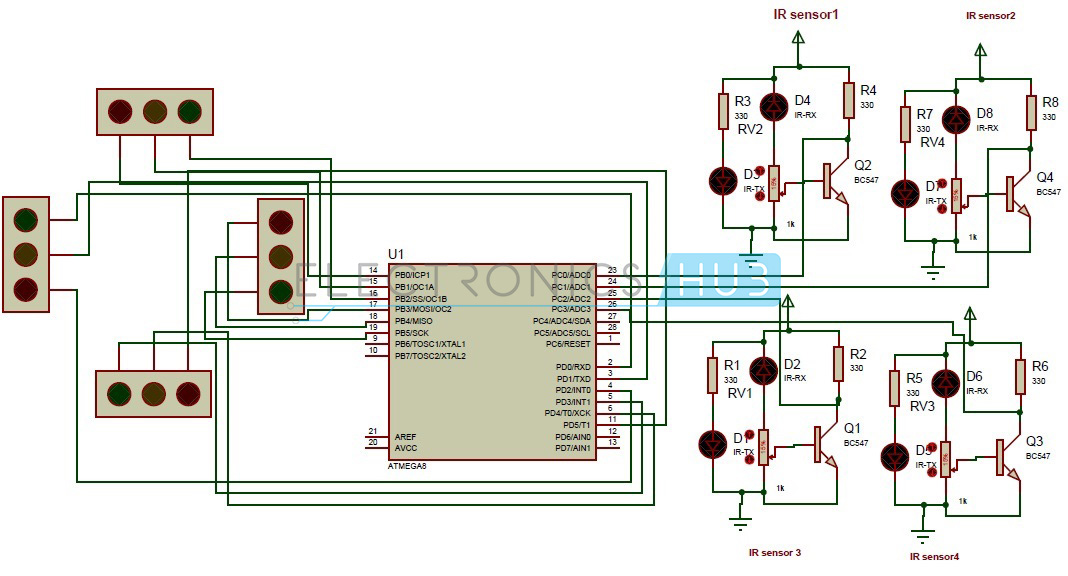
The main heart of this traffic system is microcontroller. IR sensors are connected to the PORT C (PC0, PC1, PC2, and PC3) of the microcontroller and traffic lights are connected to PORT B and PORT D. If there is a traffic on road then that particular sensor output becomes logic 0 otherwise logic 1. By receiving these IR sensor outputs, we have to write the program to control the traffic system.
Also Read the Post – How IR Sensor Based Car Parking Guard Works?
If you receive logic 0 from any of these sensors, we have to give the green signal to that particular path and give red signal to all other paths. Here continuously we have to monitor the IR sensors to check for the traffic.
Density Based Traffic Signal System Circuit Diagram:
Circuit Components:
- ATmega8 controller
- PCB board
- IR sensors -4
- LED’s-12(4-red,4-green,4-yellow)
- 12v Battery or adaptor
- Serial cable
- Connecting wires
Density Based Traffic Light Control System Circuit Design:
This circuit consists of 4 IR sensors, atmega8 microcontroller, 4 traffic lights.
IR transmitter looks like an LED. This IR transmitter always emits IR rays from it. The operating voltage of this IR transmitter is 2 to 3v. These IR (infra red) rays are invisible to the human eye. But we can view these IR rays through camera.
IR receiver receives IR rays that are transmitted by IR transmitter. Normally IR receiver has high resistance in order of mega ohms, when it is receiving IR rays the resistance is very low. The operating voltage of IR receiver also 2 to 3V.
[Also Read: How To Make an Adjustable Timer ]
We have to place these IR pair in such a way that when we place an obstacle in front of this IR pair, IR receiver should be able to receive the IR rays. When we give the power, the transmitted IR rays hit the object and reflect back to the IR receiver.
Instead of traffic lights, you can use LEDs (RED, GREEN, YELLOW). In normal traffic system, you have to glow the LEDs on time basis. If the traffic density is high on any particular path, then glows green LED of that particular path and glows the red LEDs for remaining paths.
In normal traffic system, we allow the traffic for a time delay of 1 minute for each path.
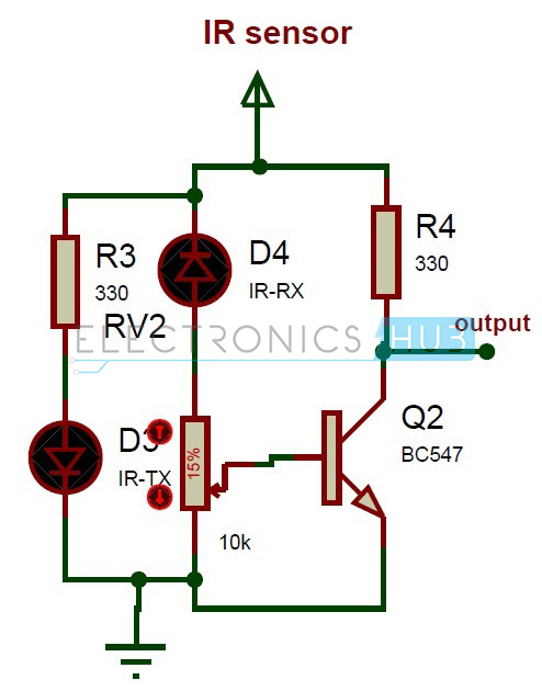
The above figure shows the IR sensor circuit. Here 330 ohm resistor is used to drop the voltage otherwise IR transmitter may get damaged. To vary the obstacle sensing distance, we have used a potentiometer. We have taken the ouput from transistor collector. This sensor gives the digital output.
Density based Traffic Signal System Circuit Simulation Video:
DOWNLOAD PROJECT CODE
How to Operate Density based Traffic Signal System Circuit?
- Connect 12V battery or adaptor to the development board.
- Switch on the supply.
- Burn the program to the ATmega8 microcontroller by keeping the programming switch sw2 in program mode.
- Connect four IR sensors to PORT C.
- Connect LEDs to PORT B and PORT D.
- Arrange all this LED’s same as like traffic lights.
- Arrange one IR sensor for each road.
- Now you can see the normal traffic system based on time basis.
- Now if you place any obstacle in front of any IR sensor, then the system allows the traffic of that particular path by glowing GREEN light.
- Finally, turn off the board power supply.
Density based Traffic Signal System Project Output Video:
Limitations of this Circuit:
- IR sensors sometimes may absorb normal light also. As a result, traffic system works in improper way.
- IR sensors work only for fewer distances.
- We have to arrange IR sensors in accurate manner otherwise they may not detect the traffic density.
115 Responses
What will be the range of IR sensors.
Here, the range of IR sensors is 10cm and it is a prototype circuit. In real time, we use different sensors for traffic signal system.
i want to do this project so now i need internal circuit so please provide me madam
Sir,
please told me the IC program language
It is a prototype circuit so we use IR sensors which range is 10cm.But in real time which sensor is used.what is the program and how I got the program of microcontroller on density base traffic control.
In real time applications you can use IR detectors, which has a range of about 100m
Is this project completely based on Electronic components?
can i know the block diagram of this system?
does this ckt diagram works if i want use two IR sensors at each path of traffic light system and if not works them what modifications needed to do so .
if u know that kind circiut then send it to me please .
good
Thank you so much for your comment, we love your support, keep following us at facebook.com/electronicshub.org.
If we want to connect 8051 in this circuit … it is possible or not ?
if it is possible then what changes should be done in circuit diagram ?
Send me abstract n cost for the following project:
Density Based Traffic Signal System using Microcontroller
We are not selling any projects, we love to educate students through this blog.
Thank you.
Dear sir, what will happen if the traffic is high from all the ends, i mean if IR sensor detect traffic from the four side or more then one side at the same time.
Thanks
‘I want to make it for semester final project and i want to make it as same as it is.
in this project we can use micro controller 8051 or not ? if the answer is yes then what could be circuit diagram ?
Im going to do project on title “Density based traffic light control”
My questions are as follows
1. What type of sensor can be used for density based traffic signal control project?
2.If the density on all roads are same means what will happen?
3.If there is a political procession and thousands of people gathered in a road means how IR sensor differentiate vehicle from people? Also in case of above situation will IR sensor detect that crowd as density ?
4. please send me program of microcontroller for this project..
please if anyone knows answer for those questions, please do reply…
I want to complete this project within a weak..So please help me..
Thankyou.
what is advantages or disadv and application………….
I would like to get your guys’ code. I have been making the same thing for my class’s final project using an arduino board with an atmega controller but I can’t get the case and break statements right. It would be helpful if I could have a look at your code to debug mine.
Much appreciated.
plz send me code of this project
I am doing same project using ARM Processor that is FRDMKL25z , I want to know about coding in that.