In the Arduino Real Time Clock Tutorial, we will learn about Real Time Clock (RTC) and how Arduino and Real Time Clock IC DS1307 are interfaced as a time keeping device. If you recall, we have already implemented an Arduino Alarm Clock using RTC DS1307 in an earlier project.
But that project didn’t cover the basics of Real Time Clock or RTC, the specifications of DS1307 RTC IC and how to interface a Real Time Clock like DS1307 or DS3231 with Arduino.
Overview
An RTC or Real Time Clock is a Timekeeping device, usually in the form of an Integrated Circuit (IC). An RTC is battery powered and keeps track of the current time even when there is no power.
Real Time Clock ICs are present in computers, servers, many embedded systems and in fact they are used wherever it is required to keep an accurate time.
Also read: ARDUINO ALARM CLOCK
Why do we need a Real Time Clock (RTC)?
Even though Arduino and almost all microcontrollers have built-in timers and timekeepers (millis () in case of Arduino), they are power dependent i.e. they run as long as there is power supply. Once the power is turned off (manually or due to power outage), all the timers are reset to 0.
While timekeeping using internal timers is acceptable for simple projects, we need an alternative in projects like data loggers, clocks, alarms, etc. where the timer runs independently irrespective of the external power or if the Microcontroller (or Arduino) is reprogrammed.
Here comes the use of Real Time Clock ICs. Almost all RTC ICs are low-current devices that run for years on a single lithium cell (usually CR2032). One of the popular and most commonly used RTC ICs is the DS1307 Real Time Clock.

DS1307 Real Time Clock
The DS1307 RTC is a low cost, low power real time clock IC that can maintain full clock and calendar i.e. hours, minutes, seconds as well as year, month and day. Some of the well-known features of the popular DS1307 RTC are mentioned below.
- Complete Timekeeping functionality i.e. hours, minutes, seconds, year with leap-year, month, date of the month and day of the week.
- Valid up to the year 2100.
- Low power consumption: consumes less than 500nA while operated on battery.
- Automatic switching to battery supply in case of power failure.
- 24 – hour or 12- hour clock with AM/PM indicator.
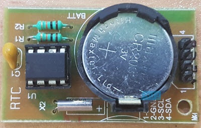
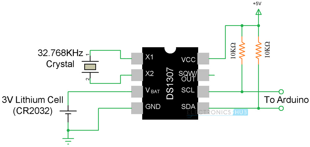
DS1307 RTC is available as modules, which consists of all the necessary components like Battery, connectors, pull-up resistors and crystal. One such module is used in this project and is shown below.
DS1307 RTC Pin Diagram
The following image shows the pin diagram of the DS1307 RTC IC. In order to reduce the power consumption, the number of pins on the IC has to be reduced. Hence, DS1307 RTC used I2C Communication.
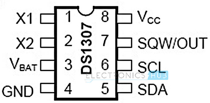
Pin description of DS1307 RTC
- X1 and X2: These are pins for connecting the crystal of frequency 32.768 KHz to enable the internal oscillator. If an external oscillator is connected to X1, then X2 can be left floating.
- VBAT: Battery Power Supply Pin. Must be connected to a 3V Lithium cell for backup supply.
- GND: Ground Pin.
- SDA: Serial Data Pin. It is the Data Input/Output pin of the I2C Interface. An external pullup of 5V is required, usually through a 10KΩ Resistor.
- SCL: Serial Clock Input Pin. It is the clock input pin of the I2C Interface. It must also be pulled up to 5V through a 10KΩ resistor.
- SQW/OUT: Square wave output pin. If not used, it can be left floating.
- VCC: The main supply pin.
Arduino Real Time Clock DS1307 Interface
Now that we have seen a little bit about the Real Time Clock IC DS1307, we will proceed with the interface of Arduino and Real Time Clock. As mentioned earlier, the DS1307 RTC Module uses I2C Communication.
In the Arduino Real Time Clock I2C interface, the Arduino Microcontroller always acts as Master and the DS1307 acts as Slave. The Master in I2C Communication i.e. Arduino in this case, is responsible for clock signal, bus access, start and stop signals.
Circuit Diagram
The following image shows the circuit diagram of the Arduino Real Time Clock DS1307 Interface. This circuit explains just the basic connections with respect to a DS1307 Module (a board that contains the DS1307 IC along with the crystal, Battery and pullup resistors).
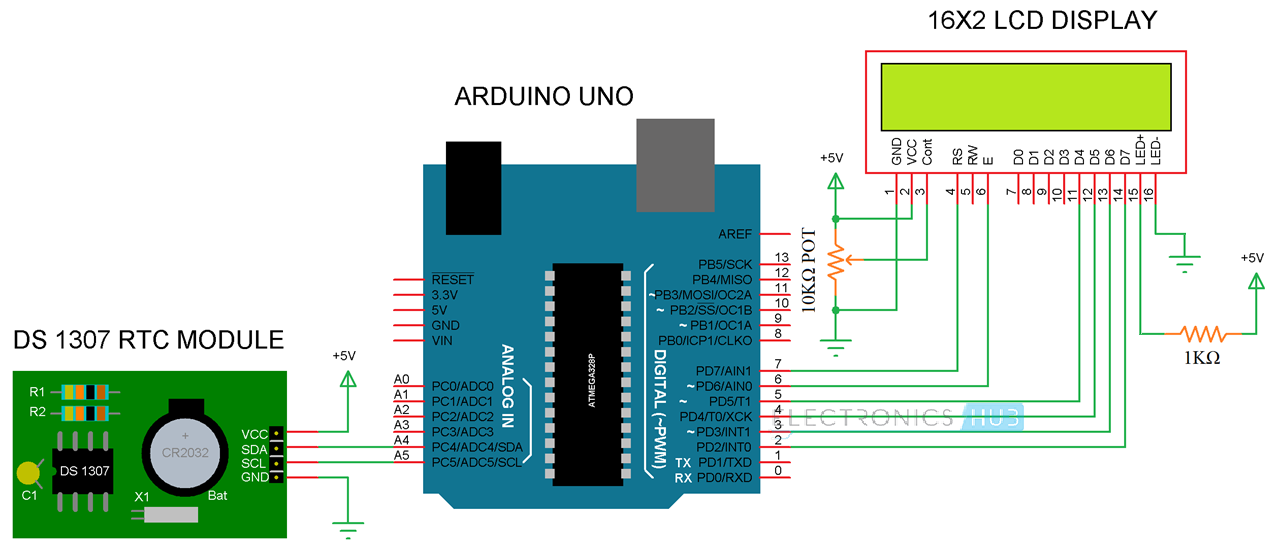
In order to understand better about the DS1307 RTC Module, the following image will help you as it contains the circuit of a typical DS1307 Real Time Clock Module.
Components Required
- Arduino UNO [Buy Here]
- DS1307 RTC Module
- 16×2 LCD Display [Buy Here]
- Breadboard
- Connecting wires
- Power supply
Circuit Design
The design of the Arduino RTC Interface is quite straight forward. Connect the SDA and SCL pins of the DS1307 RTC to the SDA and SCL pins of Arduino i.e. pins A4 and A5.
A 16×2 LCD is connected in order to display the data and time information. The connections are made as per the circuit diagram.
Working of Arduino Real Time Clock DS1307 Interface
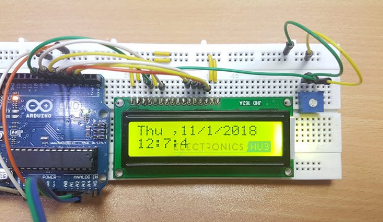
A simple project where Arduino UNO is interfaced with DS1307 Real Time Clock is implemented here. In this project, we will be programming the DS1307 RTC with current date and time and see whether it actually keeps that data even if the power supply to Arduino is removed.
A special library called “RTClib” is used in the programming and it can be downloaded from this link. Make sure that it is downloaded first and added to the Arduino library database.
In order to upload the data and time into the DS1307 RTC IC, we have used a feature available in the RTClib library, where the Arduino will upload the date and time from the computer while uploading the code.
Code
Applications
- With the help of Arduino Real Time Clock interface, we can implement several project related to data logging, alarms, clock, etc.
- Since the RTC Module DS1307 is backed with a battery, it will continue to maintain time even in the event of power fail.

28 Responses
Are you making money off the “start download view Pdf” button. I don’t want to get another app that clunks up my computer with a homepage etc.
The article on the DS1307 RTC says I can download the RCTLIB that’s needed but no where can I find that lib to download. This is not what I expected when I added your article to my pinterest board. So far I am not impressed with this website.
Did not understand anything from your first paragraph.
The link for the “RTClib” library is provided in the “Working” section.
I want this project
Can we connect +5v to arduino +5v pin
Yes. You can.
How to make clock using arduino with 7 segment display. please provide schematic diagram and program.
i want to make a device which i need automatically On and Off at a predetremined time. pls help me how to make it using RTC chip.
can i connect i2c display along with RTC?????
Yes … you can.
Hello,
the program is compiling and uploading well, but I have nothing on the display !
The wiring seems to be ok as well.
Help please, thanks
Hello,
Program is compiling and uploading well but I still have nothing on display; only a line with square blocks.
Can you help ?
thank you
Double check the connections. Adjust the Potentiometer of the LCD to adjust the contrast.
Its still not working
Yeah it won’t show up until and unless you provide the ground connection to RW pin of LCD..
Explained so neatly. Thank you Team.
programming not verify …..
RTC_DS1307 does not name type
Yeh, I had that too. In the library, the relevant class has been renamed.
Replace “RTS_DS1307” with “DS1307” and it should compile fine.
sir i can’t view the code..can you please reply it to my comment..thank you
Hello Ravi.
How can I set the RTC clock with time, day, month and year?
Best regards, Torsten
after removing supply from arduino time is not correct.it shows me the past time when i had uploaded the program each time. ie. its not showing the correct supply after power failure. what is the problem.
Hi Ansari
Hope this helps
i use a RTC_DS1307 with Arduino pro mini 3.3v and had the same problem, time was correct after programing the arduino but when power is lost and restored RTC time returns to the time of the last program upload.
What i did:
uplaod program again to set RTC time to current time
then unplug I2C wires to RTC while power is on
change program so time is not updated anymore as below
//rtc.adjust(DateTime(F(__DATE__), F(__TIME__)));//auto update from computer time
then upload new program that does NOT set the time
then remove power from project
then connect I2C lines correctly to from arduino to RTC
then power project again
this process should be done with full batter installed in RTC and repeated if date is lost in future
Hi Ravi, after connecting everything on a breadboard, and loaded up the sketch, what was oke, i just see one line with block (squares).
I did check alot of time the wireconnection, changed the LCD 1602A, but nothing: no time at all….
is there something that i forgot maybe?;;;;;;;
grts
Guido
hi thank u very much
working good. but one issue available , In seconds section is showing on 01-10 on that time.
for example 11:12:04 it is correct format , but it showing 11:12:49
please give a solution
thanks i have used this project and it work.
Thanks for sharing the project!
Could you please let me know what software you used to draw the electrical diagrams? Thanks!
How or what is the code/program started, because I got the code verified and compiled on to my board but I’m not sure how to start it
Never mind I’ve got it working!
This is my code to run servo motor. but i am not getting output.
Can anyone please help me to come out of this problem?
#include
#include “RTClib.h”
#include
int servoPin = 11;
Servo servo;
int angle = 0;
int Hour;
int Min;
int Sec;
RTC_DS1307 rtc;
char daysOfTheWeek[7][12] = {“Sunday”, “Monday”, “Tuesday”, “Wednesday”, “Thursday”, “Friday”, “Saturday”};
void setup ()
{
Serial.begin(9600);
delay(3000); // wait for console opening
servo.attach(servoPin);
if (! rtc.begin())
{
Serial.println(“Couldn’t find RTC”);
while (1);
}
if (!rtc.isrunning())
{
Serial.println(“RTC lost power, lets set the time!”);
// Comment out below lines once you set the date & time.
// Following line sets the RTC to the date & time this sketch was compiled
rtc.adjust(DateTime (2021,2,6,8,59,00));
// Following line sets the RTC with an explicit date & time
// for example to set January 27 2017 at 12:56 you would call:
// rtc.adjust(DateTime(2017, 1, 27, 12, 56, 0));
}
}
void loop ()
{
DateTime now = rtc.now();
Serial.println(“Current Date & Time: “);
Serial.print(now.year(), DEC);
Serial.print(‘/’);
Serial.print(now.month(), DEC);
Serial.print(‘/’);
Serial.print(now.day(), DEC);
Serial.print(” (“);
Serial.print(daysOfTheWeek[now.dayOfTheWeek()]);
Serial.print(“) “);
Serial.print(now.hour(), DEC);
Serial.print(‘:’);
Serial.print(now.minute(), DEC);
Serial.print(‘:’);
Serial.print(now.second(), DEC);
Serial.println();
Hour = now.hour();
Min = now.minute();
Sec = now.second();
if ((Hour== 9 && Min== 0 && Sec== 2)||(Hour== 21 && Min== 0 && Sec== 2))
{
Serial.println(“Servo motor is running”);
// scan from 0 to 180 degrees
for(angle = 0; angle 0; angle–)
{
servo.write(angle);
delay(15);
}
}
delay(10000);
}