We usually turn ON the lights in our houses and offices manually. We need to turn ON the lights only when it is dark. So, how will that be if we make a circuit which turns ON the lights automatically when it is dark? In this article, we shall see how to automatically turns ON our domestic lights automatically when it is dark.
Auto Night Lamp Using High Power LED
Auto Night Lamp Using High Power LEDs is a circuit which turns ON the LED lights interfaced to it at night time and it turns OFF the lights automatically when it is day. Usage of LEDs is growing day by day due to the advantages they provide compared to the conventional filament bulbs or fluorescent lamps. They provide good quality of white light with a better intensity compared to others. They also consume less power compared to their alternatives.
This circuit explain the light intensity control of night lamp using high power LEDS.The element which is used for sensing light in the circuit is the light dependent resistor. The resistance of the light dependent resistor depends on the light incident on it. If the intensity of light incident on it is more, then the resistance of the circuit decreases. If the intensity of light incident on it decreases, then the resistance of the device increases. We are making use of this property of the light dependent resistor to detect the light and thereby operate the LEDs. We are arranging twenty five light emitting diodes in an array such that five LEDs are in series and five such series LEDs are arranged in parallel.
Do you know about How a Light Activated Switch Circuit Works?
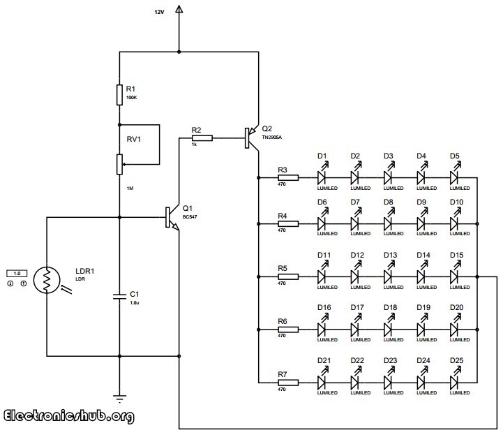
Circuit Diagram of Auto Intensity Control of LED Lights
Auto Night Lamp Working
The transistors are used in saturation mode. They are used as electronic switches in this mode. The transistor BC547 is a general purpose NPN transistor which is used to further switch the LEDs. This is a power transistor with a heat sink. The heat sink helps the transistor to dissipate the generated heat into air so that the transistor can handle higher power loads than it can do without the heat sink.
The entire circuit along with the LEDs is powered by a 12V DC power supply. A battery based DC power supply is usually preferred. However, you can use a ac rectified and regulated power supply.
The LEDs used in the circuit are high powered white LEDs. The intensity of light produced by these LEDs equals an ordinary fluorescent bulb. The lighting produced is sufficient for reading or to do any other daily activity. The circuit can be assembled on a printed circuit board with all the components neatly arranged and the LEDs placed in order. Try to place the LEDs maintaining a distance of about 1 cm between the LEDs so that the the lighting will be well distributed in your room.
Intelligent Unambiguous Night Lamp Switcher
While making a night lamp switcher, there are many aspects which needs to be taken into consideration without which there is a possibility of destroying the home appliances and lights. In this circuit, strict measures are taken to ensure that the lights to be operated are not damaged because of switching. In general, if we make a simple automatic night lamp switcher, it may turn ON the lights when it is dark. But here comes a problem. When the level of darkness is approaching, the circuit may get successive signals of dark and light with little time intervals. This may cause the circuit to repeatedly turn ON and OFF the lights at a high frequency which can possibly damage our lights within a few minutes or hours. This happens every time at evening as well as in the morning when the light intensity crosses a value for which our circuit is sensitive and toggles the switch.
In this circuit, it is not only a simple automatic light switching circuit, but also that it avoids repeated frequent switching of the devices which is usually ignored in most similar circuits but may have a detrimental effect on our operating devices. In this case, the lights. This is why the circuit is named as intelligent unambiguous night lamp as it intelligently switches the lights by avoiding repeated switching caused by unambiguity.
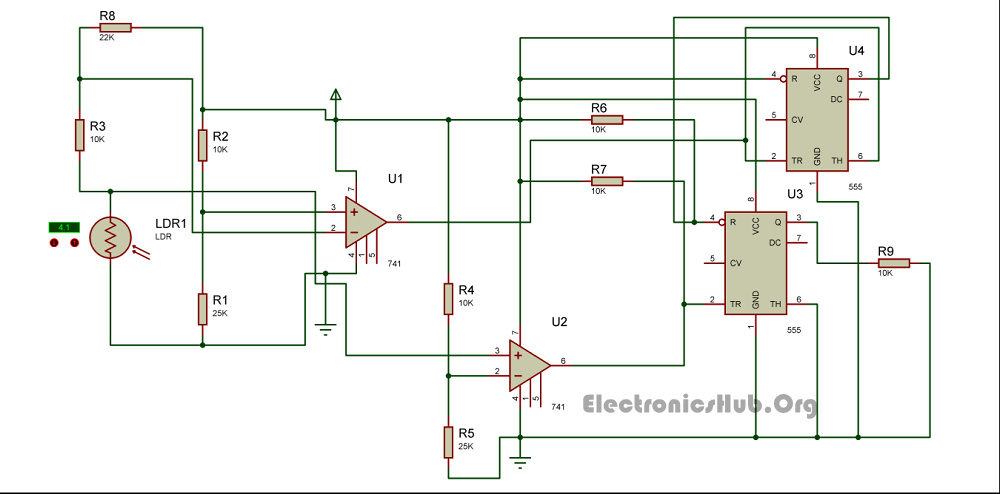
Circuit Diagram for Unambiguous Night Lamp Switcher
How to Operate this Night Lamp Switcher Circuit?
The circuit has two photo sensing devices which detect two levels of intensities. Light Dependant Resistors are used as photosensitive devices in this circuit. The light dependent resistor used with an op-amp as comparator detects the level of light intensity. The U1 IC 741 produces an output which is the first light intensity and the U2 IC741 detects the second light intensity. These two light intensities are used to calculate when the lights should be On and when they should be Off without producing unambiguous signals.
The two light detecting modules are arranged in such a way that when the first light intensity (dark point 1) is detected, the circuit turns On the relay and hence the lights will turn On. The circuit will turn Off the relay back again when both the light detecting modules detect light. This makes it eliminate ambiguities. There may be simpler circuits which detect darkness and turn On the lights but most of them fail to eliminate undesired repetitive switching. This circuit does a wonderful job by eliminating undesired switching effects.
The 555 IC U3 is in the bistable mode whereas the IC U4 acts as a buffer. The output of first IC 741 is given to the reset pin of the bistable IC whereas the output of second light detecting module with IC 741 is given to the set input of the bistable multivibrator.
Related Posts:

46 Responses
I LIKE VERY MUCH , IT HELPED ME A LOT.
bro ……..help us also……..we also need to make the same project so if u can help us
bro ……..help us also……..we also need to make the same project so if u can help us
we are definitely here to help you.
are you guys getting any problem in this circuit?
what is RV1 in the circuit??
VARIABLE RESISTOR 1M OHM
when the lights turn off,will the current flow still?
Can you please tell me indetail about the components used in this AUTO NIGHT LAMP USING HIGH POWER LED..??
Why is the capacitor is connected in parallel with the LDR which is inturn connected to base of Q1?
the circuit is very finising isthe ldr.
new innovative idea i like it so much it will help me in future
is the capacitor have polarity or not
Yess it will have polarity
LDR1 stand for what? tq..
Light dependent Resistor
hi.i m 1st year student there is a project show in my clg…pls help me with a suitable project
TEMPERATURE CONTROLLED FAN
bro pls tell me about this project
temperature controlled fan
when the lights turn off,will the current flow still?
Ya it will flow for few seconds
Wat is Rv1 in the circuit?
RV1 is a variable resistor of 1 mega ohm
pls tell me about this project
temperature controlled fan
what is the total cost of this project?
5 (white) leds in series will add up to requiring more than 12v. Also, a couple volts might be needed for the transistor.
Can i ask what high power LED is used. A picture or detaisl of its kind would be good for ref.
you can use 1 watt LED
Please send me the circuit diagram and some video or something and the list of things needed to make it . And if the things are available in a kit or we would have to buy it separately .
Can I use a 24v DC at the night lamp? reply asap pls.
In the place of variable resistor can we use a fixed resistor of 1mega ohms?
In the unambiguous night lamp switch circuit where should I connect led?
Whats is lumled???
Can I use normal led?
where can i get ldr for thise
amazing circuit. the second circuit has no LED attached, like in the first one. how can we implement the LEDs on the intelligent night lamp switch? thanks as you help.
tn2905a equivalent ????
What would be the requirements of raw material as I have to built it from crash!?
Incomplete details
Can i use P2n222 or other PNP Transistor At the place of Q2
I think P2N2222 is NPN. You can use other PNP Transisors (check for the ratings).
Nice post. I learn something new and challenging on blogs I stumbleupon every day.
It’s always helpful to read articles from other authors and practice something from their websites.
Thanks verry interesting blog!
nice project,, can you give me a list of all the components used in the auto controlled high powered led circuit
components,
– any LDR with light resistance of 10LUX (2-5 KΩ)
– 1 x 1uf cap
– 1 x 100KΩ
– 1 x 1M POT
– 1 x BC547
– 1 x 1KΩ
– 1 x TN2905A
– 5 x 470Ω
– 25 x 1.5V LED
For the intelligent unambiguous night lamp switcher which 555 timer IC output is used as input for the night lamp?
How NE555 working at night switcher?
Plis tell me how NE555 works in this circuit (switch)