In this project, we will learn about HC-05 Bluetooth Module, how to interface this Bluetooth Module with Arduino and how the HC-05 Bluetooth Module can be used for controlling the Arduino Board over Wireless Communication (Bluetooth).
Introduction
Bluetooth Communication is a 2.4GHz frequency based RF Communication with a range of approximately 10 meters. It is one of the most popular and most frequently used low range communication for data transfer, audio systems, handsfree, computer peripherals etc.
Coming to usage of Bluetooth Communication in DIY projects, HC-05 Bluetooth Module is the go to device. I have implemented several projects using HC-05 Bluetooth Module like Robotic Arm, Home Automation, LED Matrix etc.
But in all those projects, I have not discussed a lot about the Bluetooth Module, except for what is required to get the project done. So, in this project/tutorial, I will talk a little bit about the HC-05 Module.
A Brief Note on HC-05 Bluetooth Module
If you take a look around the electronics DIY and hobbyists community, HC-05 Bluetooth Module is the device of choice for implementing Bluetooth Communication based projects. HC-05 Bluetooth Module is a simple Wireless Communication device based on the Bluetooth Protocol.
This module is based on BC417 Single Chip Bluetooth IC that is compliant with Bluetooth v2.0 standard and with support for both UART and USB interfaces.
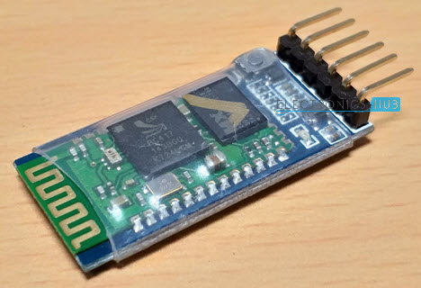
Generally, the HC-05 Bluetooth Module, or the HC-05 Sub Module, to be precise, comes with the BC417 IC along with a flash memory. Such Modules come as surface mount board and several third-party manufacturers use these board to build a more complete system with necessary pins and components.
The following image shows one such HC-05 Bluetooth Sub Module (the green board mounted on the blue board) being used as a part of a complete Bluetooth Module.
Pins of HC-05 Bluetooth Module
The HC-05 Module supports for UART, USB as well as SPI communication and depending on the application, necessary pins can be used. In my case, the board uses the UART communication.
Coming to the pins of the Bluetooth Module, generally, four pins are sufficient for successfully enabling a wireless communication link but the modules produced now-a-days come with six pins namely: VCC, GND, TX, RX, EN and STATE.
Image below shows the pins and other components on a typical HC-05 Bluetooth Module.
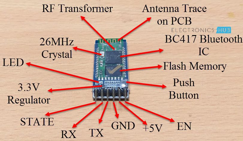
An important point to remember is the HC-05 Bluetooth Module works on a logic level of 3.3V. Hence, a 3.3V Regulator is used on the board.
NOTE: The button present on the board is used to configure the Bluetooth Module in AT Command Mode. This part of the Module is not discussed in this project.
Pin Description
- EN: It is the enable pin. When this pin is floating or connected to 3.3V, the module is enabled. If this pin is connected to GND, the module is disabled.
- +5V: This is the supply pin for connecting +5V. As the Module has on-board 3.3V regulator, you can provide +5V supply.
- GND: It is the ground pin.
- TX: It is the Transmitter pin of the UART Communication.
- RX: It is the Receive Pin of UART.
- STATE: This is a status indicator pin. This pin goes LOW when the module is not connected to any device. When the module is paired with any device, this pin goes HIGH.
NOTE: The on-board LED is used to indicate the status of the connection. When the module is not paired, the LED blinks or flashes repeatedly. Once the module is paired, the LED blinks at a constant delay of 2 seconds.
Modes of Operation
The HC-05 Bluetooth Module can be configured in two modes of operation: Command Mode and Data Mode.
In Command Mode, you can communicate with the Bluetooth module through AT Commands for configuring various settings and parameters of the Module like get the firmware information, change UART Baud Rate, change module name, set it as either Master or slave etc.
An important point about HC-05 Module is that it can be configured as Master or Slave in a communication pair. In order to select either of the modes, you need to activate the Command Mode and sent appropriate AT Commands.
Coming to the Data Mode, in this mode, the module is used for communicating with other Bluetooth device i.e. data transfer happens in this mode.
Default Settings of HC-05 Bluetooth Module
The following is a list of few of the default settings of the HC-05 Bluetooth Module.
- Name: HC-05
- Password: 1234 (or 0000)
- Type: Slave
- Mode: Data
- Baud Rate: 9600 with 8 data bits, no parity and 1 stop bit
Circuit Diagram for Interfacing HC-05 Bluetooth Module with Arduino
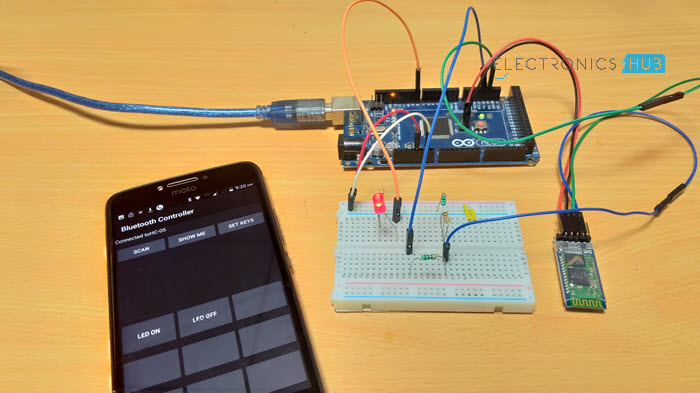
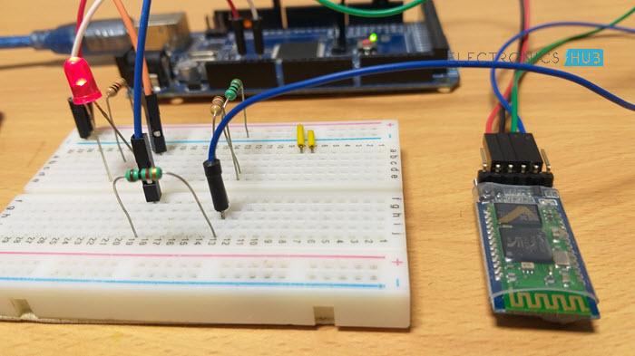
To demonstrate the connection between HC-05 Module and Arduino, I have designed a simple circuit.
The aim of this circuit is to connect the Bluetooth Module with Arduino, Pair the Bluetooth Module with an Android Phone, send data from Android Phone to the Bluetooth Module using a simple App, read the data from Bluetooth Module through Arduino and finally, display the data and control a device based on the data.
Following image shows the circuit diagram of the connection between Arduino Mega and HC-05.
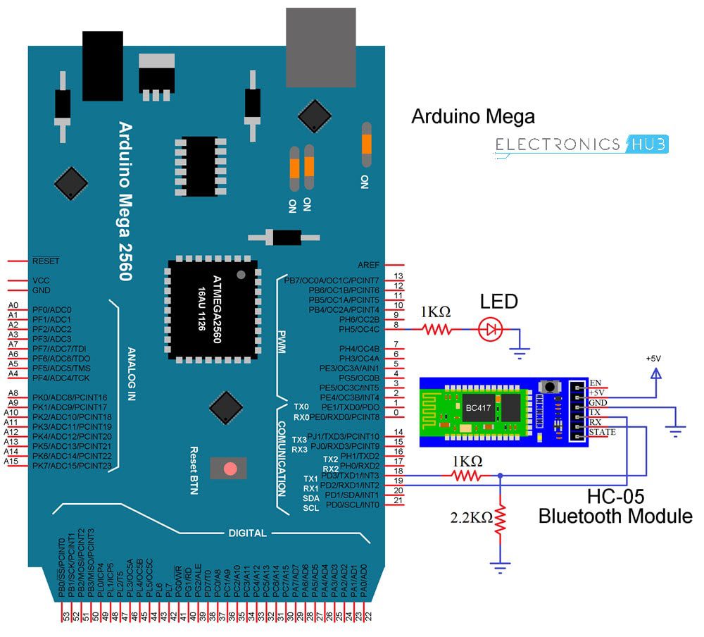
NOTE: I have gone with Arduino Mega just because it has multiple hardware UART Ports. In this project, I am using the default Serial Port of Arduino Mega for communication with the computer (Serial Monitor) and Serial 1 (RX1 and TX1 – Pins 19 and 18) for communication with Bluetooth.
Code
App for Bluetooth Communication
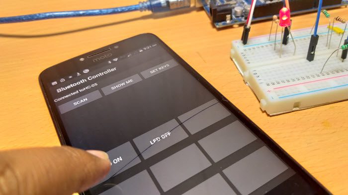
I am using a simple Android App called “Bluetooth Controller” for pairing HC-05 with my Android Phone and transmitting data. At the time of developing this project, this particular Bluetooth Controller App is no longer available in the Play Store.
But I like its simplicity and ease of use.
Connecting Phone to HC-05 Bluetooth Module
Make the connections and power on the Bluetooth Module. If this is the first time you are using your Bluetooth Module, then the LED will blink rapidly. In order to pair the module with your phone, open Bluetooth Settings in your phone and connect to “HC-05” with pin “1234”. If 1234 doesn’t work, try “0000”.
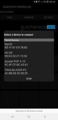
Once the Bluetooth Module is paired with your phone, you can start using the App. Open the Bluetooth Controller App and click on scan. A list of Bluetooth Devices will appear on the screen. Select HC-05.
Now, select Set Keys option in the app and enter the following information:
Key Name Data of Key
LED ON 1
LED OFF 0
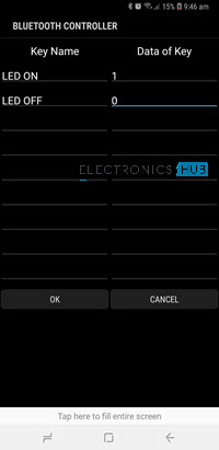
After entering this information, save it by clicking on OK. Now, on the home screen of the app, you can see two buttons (or slots) with titles “LED ON” and “LED OFF”. If you click on LED ON, ‘1’ will be transmitted over Bluetooth Communication to the HC-05 Module, which then transmits it to Arduino.
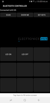
In case you click on LED OFF, ‘0’ will be transmitted. Arduino then turns ON or OFF the LED based on the received data.

One Response
Hi, I have a certain challenge with my project.
I’m trying to build a single sketch for both “master” and “slave” controllers. The only difference will be, that the “master” will have an HC-05 unit wired with the arduino, and the “slave” will not.
How can I detect in the sketch, whether a bt adapter exists / is powered or not?