In this Arduino project, we will learn about the nRF24L01 Transceiver Module, its features, specifications and finally how to enable Arduino Wireless Communication using the nRF24L01 Transceiver Module.
Introduction
Almost all the communication in the World today is wireless (at least from the end user perspective). You can find some sort of wireless communication in a variety of applications like TV Remotes, Mobile Phones, Computers, Toys, Cars, etc.
I don’t want to go into the details of Wireless Communication but you can find related information here: WIRELESS COMMUNICATION: INTRODUCTION, TYPES AND APPLICATIONS.
We have already seen a few wireless communication based projects in Electronics Hub, which are implemented using different technologies like Bluetooth, Infrared, RF (Radio Frequency) and WiFi (IEEE 802.11).
But in this project, I will be implementing an RF based Wireless Communication project using the nRF24L01 Transceiver IC. If you recall, I have implemented RF Communication in few earlier projects using the 434MHz RF Transmitter and Receiver Modules.
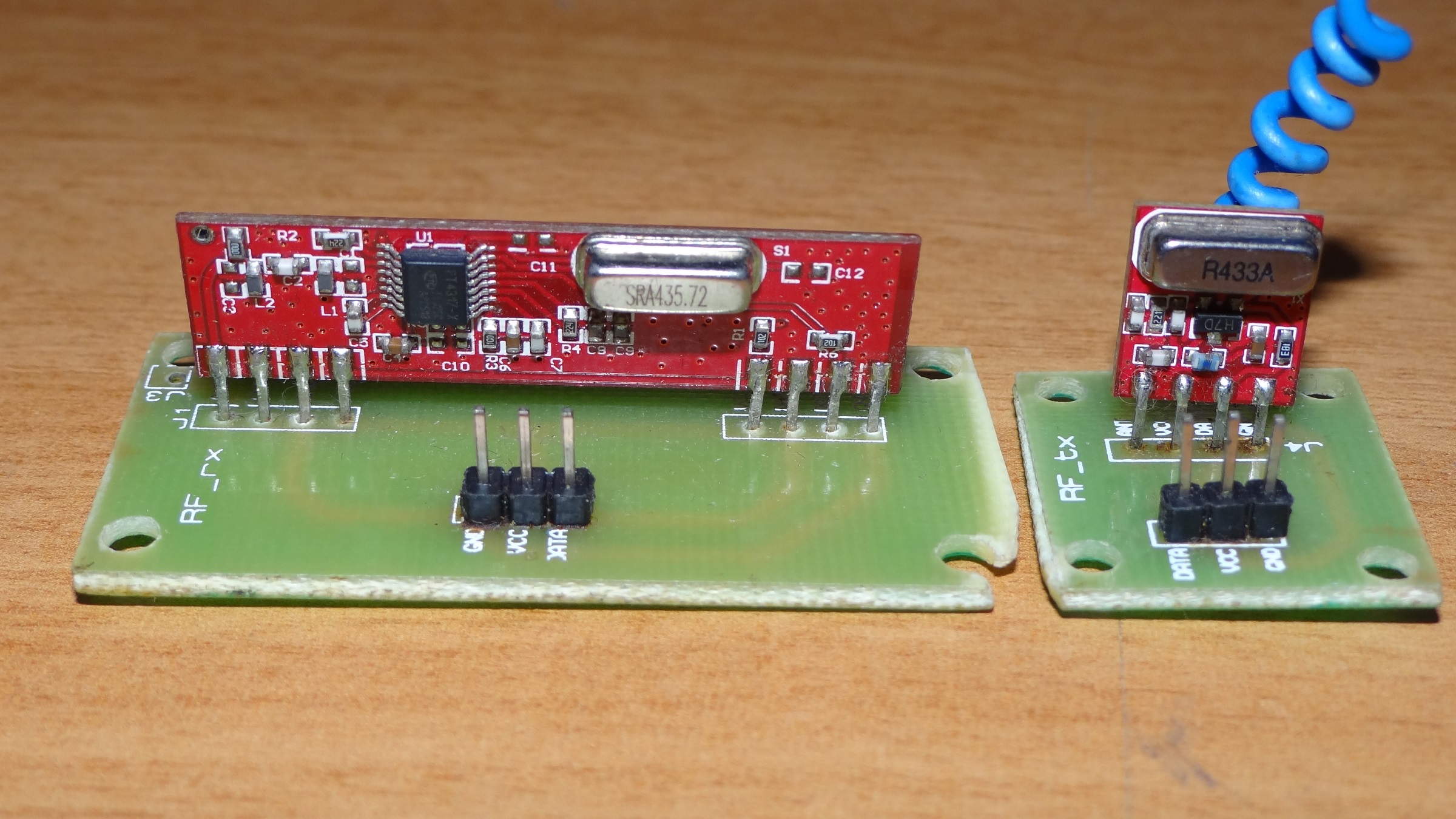
The main difference between these two RF Modules is their operating frequency. The nRF24L01 uses a 2.4GHz RF frequency whereas the earlier RF Modules used 434MHz RF frequency.
There is another important difference between them: in the 434MHz RF Modules, we have two separate modules; one for Transmission (Transmitter) and the other for Reception (Receiver). But the nRF24L0 is a Transceiver IC i.e. both the transmitter and receiver are integrated on the same IC.
A Brief Note on nRF24L01 Transceiver IC
The nRF24L01 is a single chip RF Transceiver IC developed by Nordic Semiconductor. It operates in the license-free 2.4GHz ISM band (ISM – Industrial, Scientific and Medical) with support for data rates of 250kbps, 1Mbps and 2Mbps.
For data rates of 250kbps and 1Mbps, the channel bandwidth is approximately 1MHz. So, taking the minimum and maximum operating frequencies of 2400MHz and 2525MHz, you can implement a maximum of 126 RF Channels if your data rate is limited to 250kbps or 1Mbps.
In 2Mbps data rate mote, the RF channel bandwidth should be 2MHz or more to ensure non-overlapping.
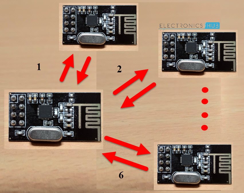
There is a special feature called MultiCeiver in nRF24L01 IC. This feature enables each RF Channel with a set of 6 unique addressed data pipes so that each module can communicate with 6 other modules in the same RF Channel.
Coming to the implementation of nRF24L01 IC, all you need is a 16MHz Crystal Oscillator, its supporting circuitry and an antenna. To design a Wireless Communication system using nRF24L01 Module, all you need is a Microcontroller, which is interfaced through Serial Peripheral Interface (SPI).
Important Features of nRF24L01 IC
- Ultra-low power operation (26μA Standby-I mode, 900nA power down mode)
- SPI Interface with Microcontroller
- Integrated RF Transmitter, Receiver and Synthesizer
- Operating voltage is 1.9V – 3.6V
- Input pins can tolerate 5V
For more information on nRF24L01, please refer to the datasheet.
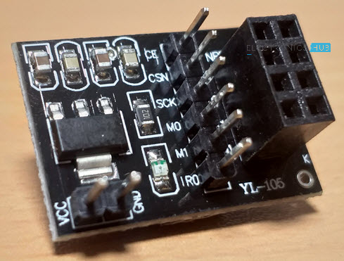
nRF24L01 Transceiver Module
Using the nRF24L01 IC, several manufacturers started developing the nRF24L0 Transceiver Module boards that contain the necessary components and pins for implementing a radio system.
The nRF24L01 Transceiver Module boards usually consists of the nRF24L01 Transceiver IC, a 16 MHz Crystal, an Antenna Trace (on the PCB), Pins for communication and power and a few passive components.
Following is the image of a typical nRF24L01 Transceiver Module board available today.
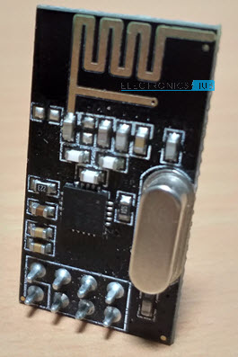
IMPORTANT NOTE: The above module and almost all the latest nRF24L01 Transceiver Modules uses nRF24L01+ IC. It is an advanced version of the nRF24L01 IC and in fact, all the discussion made is the previous section is about nRF24L01+ IC.
Components on nRF24L01 Transceiver Module
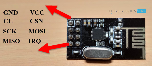
The following image shows the components on a nRF24L01 Transceiver Module board.
Pins Configuration of nRF24L01 Transceiver Module
Coming to the pin configuration of the nRF24L01 Transceiver Module, it has 8 pins. They are VCC, GND, MOSI, MISO, SCK, IRQ, CE and CSN.
- VCC: Power Supply Pin. Only 3.3V must be given.
- GND: GND pin of the power supply.
- SCK: SPI Clock Pin.
- MOSI: SPI Slave Data Input Pin.
- MISO: SPI Slave Data Output Pin.
- IRQ: Active LOW Interrupt Pin.
- CE: Chip Enable Pin.
- CSN: SPI Chip Select Pin.
Interfacing nRF24L01 Transceiver Module with Arduino
As mentioned earlier, the nRF24L01 Transceiver Module communicates over SPI Interface. So, in order to interface an nRF24L01 Transceiver Module with Arduino, you need to use the SPI Pins of the Arduino board.
Since the nRF24L01 is a Transceiver Module, you can transmit and receive data using only one nRF24L01 Transceiver Module at one end of the communication.
So, in this project, I will implement two circuits using the nRF24L01 Transceiver Module. In the first circuit, I will show you how to enable Wireless Communication between two Arduino Boards using two nRF24L01 Transceiver Modules, in which one Arduino – nRF24L01 Transceiver Module pair acts as a Transmitter while the other Arduino – nRF24L01 Transceiver Module pair acts as a receiver.
Coming to the second circuit, I will make use of the Transceiver option of the nRF24L01 Transceiver Module and implement both the Arduino – nRF24L01 Transceiver Module pairs as both Transmitter and Receiver.
But there is one important thing you need to do before proceeding with the Arduino nRF24L01 Transceiver Module interface.
nRF24L01 Transceiver Module Adapter
If you notice the nRF24L01 Transceiver Module, the pins are not breadboard friendly and connecting wires directly will not be an ideal setup.
To overcome this, you have two options. First one is to make a small perf board for inserting the nRF24L01 Transceiver Module on top and with breadboard friendly pins at the bottom.
The second option is to buy an adapter for the nRF24L01 Transceiver Module as shown in the following image.
As you can see, the adapter for nRF24L01 Transceiver Module consists of female headers for inserting the nRF24L01 Transceiver Module and corresponding male headers for connection with other boards like Arduino.
There is also a 3.3V regulator IC on the nRF24L01 Transceiver Module adapter so that you can provide 5V to the adapter (only to the adapter with 3.3V regulator and not directly to the nRF24L01 Transceiver Module itself).
Components Required
- Arduino UNO x 2
- nRF24L01 Transceiver Modules x 2
- Joystick
- TowerPro SG90 Servo Motor
- LED
- Push Button
- 1KΩ Resistor
Simple Arduino Wireless Communication using nRF24L01 Transceiver Module
Circuit Diagram
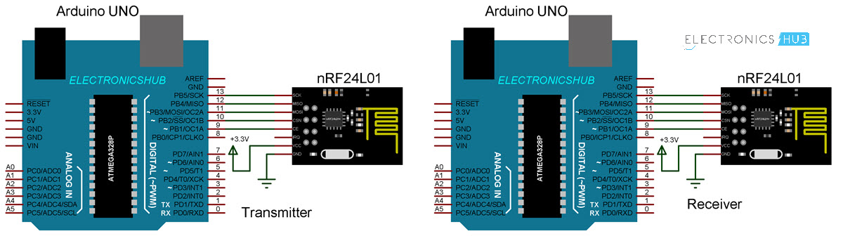
Connections
The following is the connections made between the Arduino UNO and nRF24L01 Modules at the Transmitter end.
nRF24L01 —— Arduino
VCC —– 3.3V
GND —– GND
MOSI —– 11
MISO —– 12
SCK —– 13
CE —– 9
CSN —– 10
As I have used an Arduino UNO even at the receiver end, I have used the same connection. If you are using other Arduino Boards like Mega, check for the SPI Pins.
Code
Transmitter Code
Receiver Code
NOTE: Bidirectional Wireless Communication Between Two Arduino Boards will be updated soon.

3 Responses
I tried the code you have provided. It works fine.
How do you use the RF24 library to receive acknowledgements from the receiver?
hey, i have a question… actually i don’t want to use arduino is there any similar ADC and DAC converter that can directly connected to MOSI and MISO and SCK pin (that means any SPI chip) available? like in Rf transmitter and receiver? kindly let me know thank you….
Help. I tried doing the Hello World example & there is some issue I added the capacitors checked every connection but somehow it takes around an hour of restarting & checking the connections for the modules to connect to each other & once they are connected they it’s not a problem I can disconnect them for some time & again they work but everytime I keep them disconnected for over night I have to spend an hour sometimes 2 for them to work again this has haulted all my efforts as I have classes & work during the day & every night I wana work on this my work is left incomplete as most of time is gone only to start the connections please help