In this tutorial, I have a brief overview about the Arduino Mega Pinout Board, the layout of a typical Mega board, some of the important specifications, and finally, the Arduino Mega Pinout.
I already discussed the Arduino UNO Pinout and Arduino Nano Pinout in the previous tutorials. If you are interested in those boards, then check out the tutorials.
Arduino Mega 2560 Pinout
Since the introduction of Arduino UNO as a quick prototyping board, there has been a steady need for boards with more capabilities/features than the Arduino UNO can offer. The answer to this is the Arduino Mega Board.
While Arduino Nano is a breadboard friendly version of Arduino UNO with more or less the same features, Arduino Mega is completely a different board. It can be considered as a big brother to both UNO and Nano, both in terms of size as well as features.
Arduino Mega is based on ATmega2560 Microcontroller, an 8-bit AVR Architecture based MCU from ATMEL. It is available in a 100-pin Quad Flat Package (QFP).
It is designed and developed to provide more number of IO lines (both Digital and Analog), more flash memory and more RAM when compared to UNO.
So, if you are developing some advanced robotic projects or 3D Printing hardware and want to use the Arduino environment, then Arduino Mega 2560 Pin Mapping is the board for you.
Arduino Mega Board Layout
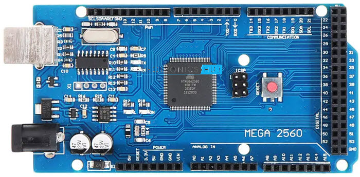
A typical Arduino Mega board’s layout is clearly shown in the following image. Unlike Arduino Nano, all the components are placed on the top side of the PCB.
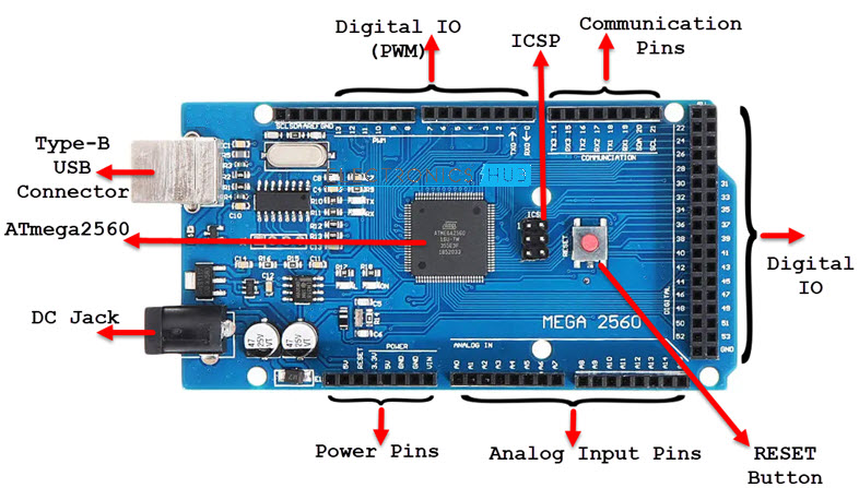
As you can notice, there is a Type-B USB connector on the left short edge of the board, which is used for powering on the board as well as programming the Microcontroller. There is also a 2.1 mm DC jack to provide external power supply. Also, the Arduino Mega’s layout is very intuitive and simple to comprehend.
I will discuss about the pins of Arduino Mega in the Arduino Mega Pinout Section.
Arduino Mega Technical Specifications
As Arduino Mega is based on ATmega2560 Microcontroller, the technical specifications of Arduino Mega are mostly related to the ATmega2560 MCU. But none the less, let me give you a brief overview about some important technical specifications of Arduino Mega 2560.
|
MCU |
ATmega2560 |
| Architecture |
AVR |
|
Operating Voltage |
5V |
| Input Voltage |
6V – 20V (limit) 7V – 12V (recommended) |
|
Clock Speed |
16 MHz |
| Flash Memory |
256 KB (8 KB of this used by bootloader) |
|
SRAM |
8 KB |
| EEPROM |
4 KB |
|
Digital IO Pins |
54 (of which 15 can produce PWM) |
| Analog Input Pins |
16 |
How to power up the Arduino Mega Pinout?
There are a couple of ways in which you can power the Mega board. The first and easy way is using the Type-B USB Connector. The next way is to provide an unregulated supply in the range of 6V to 20V to VIN pin of the Mega.
You can also supply the unregulated supply through the 2.1mm DC Jack, in which case, you can access the supplied voltage through the VIN Pin.
What are Different Memories of Arduino Mega?
Strictly speaking, this is specific to the MCU i.e., ATmega2560, used on the Arduino Mega Board. There are three different memories available in ATmega2560. They are:
- 256 KB of Flash Memory
- 8 KB of SRAM
- 4 KB of EEPROM
- 8 KB of the Flash Memory is used by the bootloader code.
What are the Input and Output Pins of Arduino Mega?
Of the 86 pins available on the Mega board, 72 pins are associated with input and output. In that 54 pins (D0 to D53) are true digital IO pins, which can be configured as per you application using pinMode(), digitalWrite() and digitalRead() functions.
All these Digital IO pins are capable of sourcing or sinking 20mA of current (maximum 40mA is allowed). An additional feature of the Digital IO pins is the availability of internal pull-up resistor (which is not connected by default). The value of the internal pull-up resistor will be in the range of 20KΩ to 50KΩ.
There are also 16 Analog Input Pins (A0 to A15). All the analog input pins provide a 10-bit resolution ADC feature, which can be read using analogRead() function.
An important point about Analog Input pins is that they can be configured as Digital IO pins, if required.
Digital IO pins 2 – 13 and 44 – 46 are capable of producing 8-bit PWM Signals. You can use analogWrite() function for this.
Communication Interfaces on Arduino Mega
Arduino Mega supports three different types of communication interfaces. They are:
- Serial
- I2C or I2C
- SPI
Perhaps the most common communication interface in the Arduino universe is the Serial Communication. In fact, the Arduino boards (UNO or Nano or Mega) are programmed using the serial communication.
Arduino Mega supports four hardware Serial Communication interfaces. Digital IO pins 0 and 1 are used as Serial RX0 and TX0 pins to receive and transmit serial data. These pins are connected to the serial pins of the on-board USB to Serial Converter IC.
Similarly. Digital IO pins 19 and 18 as RX1 and TX1, 17 and 16 as RX2 and TX2 and 15 and 14 as RX3 and TX3 respectively.
Digital IO Pins 20 and 21 can be configured as SDA (20) and SCL (21) to support I2C or I2C or Two Wire Interface (TWI) communication.
The final communication interface is the SPI. Digital IO Pins 50, 51 52 and 53 can be configured as SPI pins MISO, MOSI, SCK and SS respectively.
Additional Features
There is an on-board LED connected to digital IO pin 13. Use this LED to perform Blinky operations. The reference voltage for the internal ADC is by default set to 5V. But using the AREF pin, you can manually set the upper limit of the ADC.
Using the IOREF pin, you can set the reference voltage for Microcontroller operations.
To reset the microcontroller, you can use the on-board RESET button.
Although you can program the Arduino Mega using the USB cable, there is a provision to program the MCU using the In-Circuit Serial Programming (ICSP) interface.
The UART bootloader, which is preloaded in to the ATmega2560 Microcontroller, enables programming through serial interface. But ICSP doesn’t need any bootloader. You can program Arduino Mega using ISCP or use the ISCP of Arduino Mega to program other Arduino Boards.
Digital IO Pins 2, 3, 18, 19, 20 and 21 can be configured as External Interrupts Pins INT0, INT1, INT5, INT4, INT3 and INT2 respectively. Use attachInterrupt() function to configure the Interrupt for rising edge, falling edge or level change on the pin.
If you want use any Shields, then Arduino Mega is perfectly compatible with most of shields designed for Arduino UNO.
Arduino Mega 2560 Pinout Diagram
Now that we have seen a little bit about Arduino Mega and its important features and specifications, let us look into the Arduino Mega Pinouts. The following image shows the complete pinout of Arduino Mega Board.
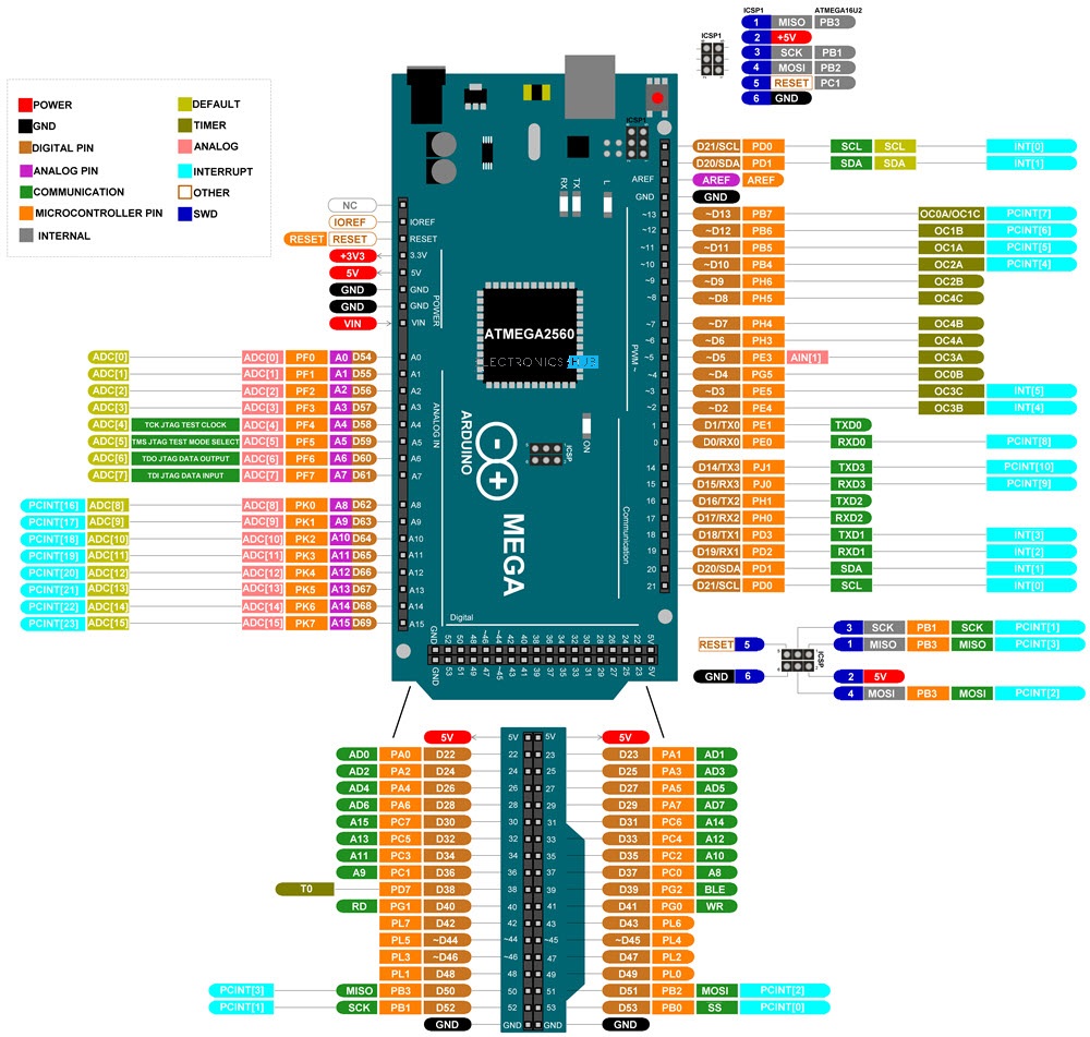
As you can see from the image, I described each pin of the Arduino Mega with its Microcontroller equivalent pin, alternative functions, default functionality and other additional features.
For higher resolution image, click here.
Arduino Mega 2560 Pinout Mapping
| Pin No. | Function | Description |
|---|---|---|
| 1 | PG5 | PWM on Digital Pin 4 |
| 2 | PE0 | Digital Pin 0 (RX0) |
| 3 | PE1 | Digital Pin 1 (TX0) |
| 4 | PE2 | XCK0/AIN0 |
| 5 | PE3 | PWM on Digital Pin 5 |
| 6 | PE4 | PWM on Digital Pin 2 |
| 7 | PE5 | PWM on Digital Pin 3 |
| 8 | PE6 | T3/INT6 |
| 9 | PE7 | CLKO/ICP3/INT7 |
| 10 | VCC | VCC |
| 11 | GND | Ground |
| 12 | PH0 | Digital Pin 17 (RX2) |
| 13 | PH1 | Digital Pin 16 (TX2) |
| 14 | PH2 | XCK2 |
| 15 | PH3 | PWM on Digital Pin 6 |
| 16 | PH4 | PWM on Digital Pin 7 |
| 17 | PH5 | PWM on Digital Pin 8 |
| 18 | PH6 | PWM on Digital Pin 9 |
| 19 | PB0 | Digital Pin 53 (SS) |
| 20 | PB1 | Digital Pin 52 (SCK) |
| 21 | PB2 | Digital Pin 51 (MOSI) |
| 22 | PB3 | Digital Pin 50 (MISO) |
| 23 | PB4 | PWM on Digital Pin 10 |
| 24 | PB5 | PWM on Digital Pin 11 |
| 25 | PB6 | PWM on Digital Pin 12 |
| 26 | PB7 | PWM on Digital Pin 13 |
| 27 | PH7 | T4 |
| 28 | PG3 | TOSC2 |
| 29 | PG4 | TOSC1 |
| 30 | RESET | RESET |
| 31 | VCC | VCC |
| 32 | GND | Ground |
| 33 | XTAL2 | XTAL2 |
| 34 | XTAL1 | XTAL1 |
| 35 | PL0 | Digital Pin 49 |
| 36 | PL1 | Digital Pin 48 |
| 37 | PL2 | Digital Pin 47 |
| 38 | PL3 | PWM on Digital Pin 46 |
| 39 | PL4 | PWM on Digital Pin 45 |
| 40 | PL5 | PWM on Digital Pin 44 |
| 41 | PL6 | Digital Pin 43 |
| 42 | PL7 | Digital Pin 42 |
| 43 | PD0 | Digital Pin 21 (SCL) |
| 44 | PD1 | Digital Pin 20 (SDA) |
| 45 | PD2 | Digital Pin 19 (RX1) |
| 46 | PD3 | Digital Pin 18 (TX1) |
| 47 | PD4 | ICP1 |
| 48 | PD5 | XCK1 |
| 49 | PD6 | T1 |
| 50 | PD7 | Digital Pin 38 |
| 51 | PG0 | Digital Pin 41 |
| 52 | PG1 | Digital Pin 40 |
| 53 | PC0 | Digital Pin 37 |
| 54 | PC1 | Digital Pin 36 |
| 55 | PC2 | Digital Pin 35 |
| 56 | PC3 | Digital Pin 34 |
| 57 | PC4 | Digital Pin 33 |
| 58 | PC5 | Digital Pin 32 |
| 59 | PC6 | Digital Pin 31 |
| 60 | PC7 | Digital Pin 30 |
| 61 | VCC | VCC |
| 62 | GND | Ground |
| 63 | PJ0 | Digital Pin 15 (RX3) |
| 64 | PJ1 | Digital Pin 14 (TX3) |
| 65 | PJ2 | XCK3/PCINT11 |
| 66 | PJ3 | PCINT12 |
| 67 | PJ4 | PCINT13 |
| 68 | PJ5 | PCINT14 |
| 69 | PJ6 | PCINT15 |
| 70 | PG2 | Digital Pin 39 |
| 71 | PA7 | Digital Pin 29 |
| 72 | PA6 | Digital Pin 28 |
| 73 | PA5 | Digital Pin 27 |
| 74 | PA4 | Digital Pin 26 |
| 75 | PA3 | Digital Pin 25 |
| 76 | PA2 | Digital Pin 24 |
| 77 | PA1 | Digital Pin 23 |
| 78 | PA0 | Digital Pin 22 |
| 79 | PJ7 | |
| 80 | VCC | VCC |
| 81 | GND | Ground |
| 82 | PK7 | Analog Pin 15 |
| 83 | PK6 | Analog Pin 14 |
| 84 | PK5 | Analog Pin 13 |
| 85 | PK4 | Analog Pin 12 |
| 86 | PK3 | Analog Pin 11 |
| 87 | PK2 | Analog Pin 10 |
| 88 | PK1 | Analog Pin 9 |
| 89 | PK0 | Analog Pin 8 |
| 90 | PF7 | Analog Pin 7 |
| 91 | PF6 | Analog Pin 6 |
| 92 | PF5 | Analog Pin 5 |
| 93 | PF4 | Analog Pin 4 |
| 94 | PF3 | Analog Pin 3 |
| 95 | PF2 | Analog Pin 2 |
| 96 | PF1 | Analog Pin 1 |
| 97 | PF0 | Analog Pin 0 |
| 98 | AREF | Analog Reference |
| 99 | GND | Ground |
| 100 | AVCC | Voltage Supply for Analog System |
Conclusion
This was a brief overview on Arduino Mega board layout, technical specifications, important features and most importantly the complete Arduino Mega Pinouts information.

2 Responses
Great article! Thank you.
I plan to use 14 PWM output pins. You state safe current per pin is 20 ma. What is the total safe current when 14 pins are being utilized?
Is it more common practice to ‘source’ 5v or to ‘sink’ 0v when the output is “high”? And am I using the proper terms in that question?
Thank you for the help.
This pinout diagram is helpful for understanding the Arduino Mega. Clear and concise information.