In this project, we will learn about LED Matrix Displays and two different projects on Arduino 8×8 LED Matrix Interface. The first project will be a simple interface between Arduino and 8X8 LED Matrix to display information (even scrolling information and images can be displayed) and the second project will be an advanced project where the 8×8 LED Matrix is controlled through an Android device.
An LED matrix is a two dimensional array of LEDs that can be used to display symbols, characters or even images. Based on the orientation of the LEDs in the matrix, there can be two types of LED matrices.They are Common Row Anode and Common Row Cathode.
Project 1: Simple Arduino LED Matrix Interface
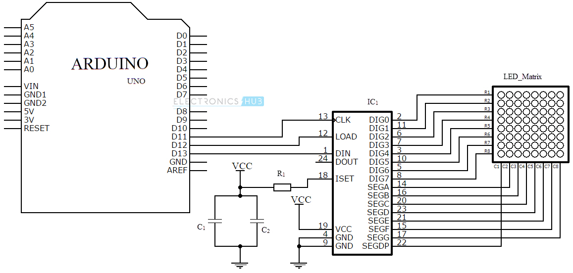
Circuit Diagram
Components Required
- Arduino Uno board [Buy Here]
- LED Matrix – 8 x 8 LED dot matrix
- IC1 – MAX 7219
- R1 – 10 KΩ
- C1 – 0.1 µF
- C2 – 10 µF
Component Description
Arduino Uno
The project is based on the Arduino Uno microcontroller board. Out of the 14 available digital input / output pins on the Arduino Uno, we need only three pins to implement this project.
One pin provides the clock signal to the LED display driver IC (MAX 7219) while another pin is used to transmit the serial data to the IC for displaying on the LED matrix. The corresponding pins must be appropriately mentioned in the program.
LED Matrix
An 8 x 8 LED matrix display is used in this project to display the information. LED matrices are available in different styles like single color, dual color, multi-color or RGB LED matrix.
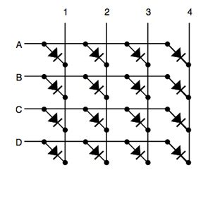
They are also available in different dimensions like 5 x 7, 8 x 8, 16 x 16, 32 x 32 etc. Based on the arrangement of the LEDs in the matrix, an LED matrix can be either common row anode or common row cathode.
In case of common row anode type LED matrix, the current sources (high or positive voltage) are given to the rows A-D and the current sinks (low or negative voltage or ground) are given to the columns 1-4.
In case of common row cathode type LED matrix, the current sources (high or positive voltage) are given to the columns 1-4 and the current sinks (low or negative voltage or ground) are given to the rows A-D.
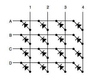
The LED matrix used in this project is a common row cathode type LED matrix. While developing the project, the type of LED matrix must be known and the program must be written accordingly.
IC MAX 7219
The LED matrix can be driven in two ways. They are parallel (where each row or column are sent with parallel data) and serial (where the data is sent serially and an IC is used to convert this serial data into parallel data).
MAX 7219 is a common cathode display driver with serial input and parallel output. It is used to interface microprocessors and microcontrollers with 64 individual LEDs (8 x 8 LED matrix for example has 64 LEDs), seven segment LED displays up to 8 digits or bar graph displays.
The 8 x 8 LED matrix is connected to the MAX 7219 as shown in the circuit diagram and the data input is received from the Arduino board to the MAX 7219.
NOTE:
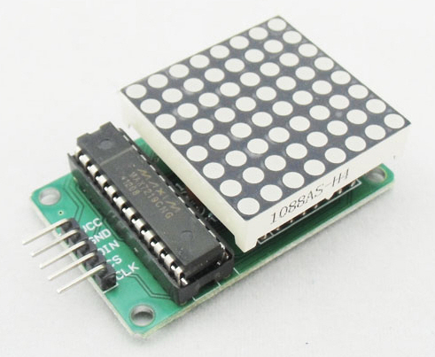
Pre-wired MAX 7219 and 8 x 8 LED matrix modules are available in the market. They can be used for convenience.
Working
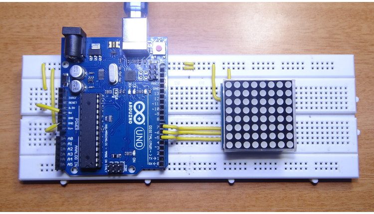
The aim of the project is to interface an Arduino Uno board with an 8 x 8 LED matrix to display information.
Even though a single 8 x 8 LED matrix with corresponding MAX 7219 IC is used in this project, multiple LED matrices can be connected in series for long scrolling display. Connect the components as shown in the circuit diagram. The working of the system is as follows.
3 of the 14 available digital input / output pins are used to control the display driver IC MAX 7219. The 3 pins on the MAX7219 IC are clock, data in and load (or cs in case of MAX 7221 IC). A maximum clock frequency of 10MHz can be applied. DIN (Data in) accepts the serial data from the microcontroller or Arduino board.
It is 16 bit long where the first 8 bits (D0 – D7) are for driving the columns (SEG A-G and DP of the MAX 7219 IC) of the LED matrix and the next 8 bits (D8 – D15) are for driving the (DIG 0-7 of the MAX 7219 IC) rows of the LED matrix.
The load pin (or CS or chip select pin in case of Max 7221 IC) latches the serial input data on its rising edge.
Another important pin on MAX 7219 is the ISET, which sets the peak current to the segment to drive all the LEDs. It is connected via a resistor (R1), which is called RSET. The capacitors filters out any noise in the supply.
When the serial data in is sent using the Arduino (through the program), the serial data is converted into segments and digits to drive columns and rows of the LED matrix. According to the data sent, the corresponding LEDs on the matrix light up and display the message.
The program written here is for scrolling text display. It might be difficult to view long scrolling data on a single 8 x 8 LED matrix. Hence, multiple LED matrices can be chained to form a long matrix.
The no. of MAX 7219 ICs are equal to the no. of 8 x 8 LED matrices. In order to extend the display to multiple LED matrices, the Data OUT (DOUT) pin of the first MAX 7219 must be connected to the Data IN (DIN) pin of the second MAX 7219 IC. This process must be continued for multiple LED matrices.
(The positioning of the LED Matrix in the chain is important. The first LED matrix must be placed at the right of the chain.)
Code
NOTE
- The program uses a library called LedControl. This library must be added to the Arduino IDE and the header file LedControl.h must be included in the program.
- The use of this library file is to enable multiple MAX 7219 ICs to be integrated and also provide scrolling text. The library can be downloaded from this link.
Project 2: Arduino 8X8 LED Matrix Interface with Android Phone
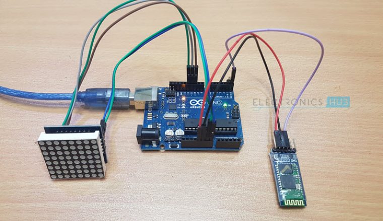
The second circuit in the Arduino 8×8 LED Matrix Interface series is based on Bluetooth Communication and Android Phone. In this project, we have interface Arduino with an Android phone using Bluetooth Communication and the 8×8 LED Matrix connected to Arduino through MAX7219 is controlled through a dedicated application on the Android Phone.
We have already seen in the previous project as how the 8×8 LED Matrix and the MAX7219 IC are connected. So, I’ll skip that part of the connection and proceed with how MAX7219 IC is interfaced with Arduino.
But I haven’t mentioned the Pin Diagram of a typical 8×8 LED Matrix in the previous circuit. So, to have a fulfilment, the following image shows the pin out of an 8×8 LED Matrix.
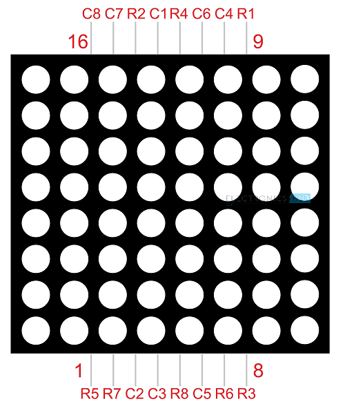
As you can observe, an 8×8 LED Matrix consists of 16 pins: 8 Rows and 8 Columns. Usually, the Rows are associated with the Anodes of the LEDs and the Columns are associated with the Cathodes of the LEDs.
Circuit Diagram
Components Required
-
- Arduino UNO
- MAX7219 IC Board
- 8×8 LED Matrix
- HC-05 Bluetooth Module
- Android Phone with App installed
Circuit Design
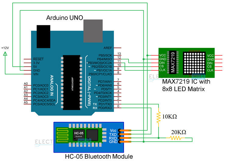
Since the communication between Arduino and MAX7219 is based on SPI Communication Protocol, all we need is three pins from Arduino (Data, Clock and Chip Select). The CS, CLK and DIN pins of the MAX7219 IC Board are connected to pins 10, 11 and 12 of the Arduino.
As we are using the Bluetooth connection between Arduino and Android device, the RX and TX pins of the HC-05 Bluetooth Module are connected to TX and RX pins of the Arduino (Pins 1 and 0).
Controlling 8×8 LED Matrix through Android App
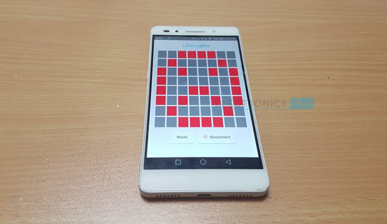
A dedicated app for Android based devices is designed for this project. The layout of the app which is already installed on a mobile phone is shown in the following image.
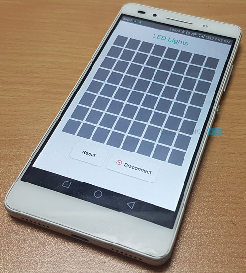
The app has 8×8 squares (each corresponding to one LED on the 8×8 LED Matrix), a Reset button and a Disconnect button. Touching a particular square will turn ON the particular LED in the 8×8 LED Matrix.
The color of the square will turn Red, as an indication that the LED is turned ON. Touching the square once again will turn OFF the corresponding LED and the color of the square will revert back to grey.
A Reset button is given at the bottom, using which you can reset the 8×8 LED Matrix i.e. all the LEDs will be turned OFF. The disconnect button will get disconnected from the Bluetooth.
NOTE: The app utilizes the Bluetooth feature of the phone. Hence, necessary permissions must be given. Also, the HC-05 Bluetooth Module must be paired with the device (Phone).
Download Android App
You can download and install the App used in this project for Android Devices. Use this link to install the App.

Code
Applications
- Arduino based 8 x 8 LED matrix display uses only 3 pins of the Microcontroller. Hence, it can be used in applications where displaying information is a part of the system in which other pins of the microcontroller can be used for other peripherals.
- LED Matrix is a basic form of display device that is used for displaying information at public places like bus or train stations.
- Multiple LED matrices can be combined to form large displays and can be used to display images with multi colors.

22 Responses
i need H file … just now dont working
the h file is given look clearly on the page
really nice..
my project has not working what i can do
This project is very nice and easy
Thank you so much!
I did it.
<3
Send me full code for this project. Email _ hay.ankitsingh@gmail.com
Hi,
we have provided everything in the website – code, link for the app.
Is Max 7219 chip compatible for 8×8 led matrix common anode displays? i need help, please share with me schematic diagram of max7219 + 8×8 led matrix common anode module. thank you
For control using app, which code i have to copy (code without the app or with app code) with the library?
Use the second code (which is below the Download App link).
Brother i am glad that you are did this great work because my teacher rejected my recent project of Mobile Phone Controlled Vehicle using bluetooth but now worries now i can buy led module and can use old components of my ex project Thank you
HOW TO CONTROL 4 MODULE OF SAME….PLEASE SEND ME CODE.
How to cascade 4 led matrix?
please provide the code
I am currently doing the one with the android phone. I’ve copied the codes and everything. I was also able to connect my phone to HC-05 with the app but the thing is that the led matrix won’t light up. Please help!!
Hi, in your schedule, I think you mixed RXD and TXD connection.
Very Nice !!
Help i’m in mirror
Hi, how can I control multiple dot matrix displays individually? By the post you’ve written, it seems like the multiple displays would display the same thing in each one
where can i get the led control h library
What is the app on android. Please tell me.
hi, i have the max7219 assembly with the chip at the side… do i have to get the one like what you used in the construction to cascade multiple matrices?