In this project, I will show you how to interface HC-05 Bluetooth with STM32F103C8T6 Blue Pill Board. By interfacing a Bluetooth Module like HC-05 or HC-06 with STM32, you can wirelessly communicate with your STM32 MCU from another Bluetooth device like a Smart Phone, for example.
As a demonstration of this project, I will control the on-board LED connected to Pin PC13 of the MCU from a Bluetooth App installed on an Android Phone.
Introduction
Bluetooth is one of the most popular wireless communication protocols used in embedded systems. Even in consumer electronics like mobile phones and laptops, it is commonly used for data transfer and audio functionalities.
In fact, with the development of BLE (Bluetooth Low Energy), the development and implementation of Bluetooth based wireless headsets is at its peak (sorry 3.5mm headphone jack fanboys, myself included!).
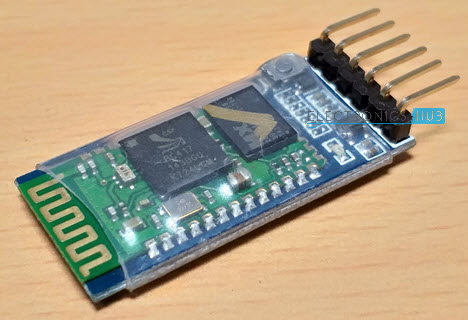
Coming to the Embedded World, the HC-05 Bluetooth Module is the most popular Bluetooth Modules being used for a long time. It is a simple UART based module that runs at the traditional 2.4GHz wireless frequency for a range up to 10m.
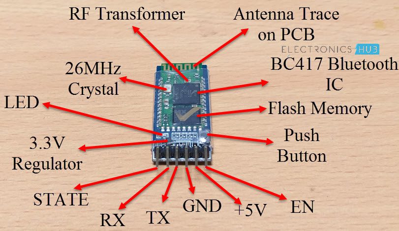
I have already implemented several HC-05 Bluetooth Module based projects. For example, in the “HC-05 Bluetooth Module” Tutorial, I have talked a deal about some basic information regarding the HC-05 Bluetooth Module, its layout on the board, its pins description and also demonstrated how to interface HC-05 Bluetooth Module with Arduino.
So, I suggest you to refer to that tutorial for additional information on HC-05 Bluetooth Module. In this project, I will be focusing on Interfacing HC-05 Bluetooth with STM32F103C8T6 Blue Pill Board.
Important Note
In the previous STM32 Tutorial, I have discussed the basics of STM32F103C8T6 Blue Pill board and also how to upload program through the USB Port of the board. I won’t be discussing those topics again. Hence, I suggest you to completely go through the previous tutorials mentioned below before proceeding further with this project.
Introduction to STM32F103C8T6 – “Getting Started with STM32F103C8T6 Blue Pill“
Program STM32 Blue Pill using USB Port – “How to Upload STM32F103C8T6 USB Bootloader?“
Also, you can use either of the programming methods i.e. the traditional UART based programming using USB to Serial Adapter or the USB Bootloader based programming through the on-board microUSB Port.
If you are planning to program your Blue Pill using UART, then please note that the same pins are being used for communication with the Bluetooth Module (Pins PA9 and PA10).
And if you are using USB Programming, then disconnect the Bluetooth Module form the STM32 Board, upload the program and reconnect the Bluetooth Module. Additionally, make sure you are setting the right BOOT Pin configurations.
Circuit Diagram
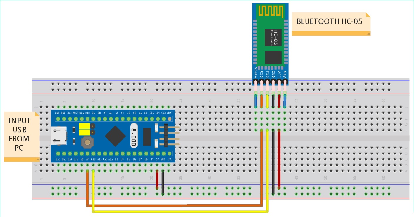
The following image shows the circuit diagram of Interfacing HC-05 Bluetooth Module with STM32F103C8T6 MCU.
Components Required
Hardware
- STM32F103C8T6 Blue Pill Board
- HC-05 Bluetooth Module
- Connecting Wires
- USB to Serial Adapter (if programming STM32 via UART)
- USB Cable
- Android based Smart Phone
Software
- Any Bluetooth Terminal App for Android Phone
I am not making any suggestions regarding the Bluetooth App and feel free to use any Bluetooth terminal App. For demonstration of the project, I used “Serial Bluetooth Terminal” by Kai Morich. If you want to use the same, use this link.
Connections Explained
The connections between STM32F103C8T6 Blue Pill Board and the HC-05 Bluetooth Module are very simple. The RX pin of the Bluetooth Module is connected to PA9 pin of the MCU and the TX pin of the Bluetooth Module is connected to PA10 pin of the MCU.
VCC and GND of the HC-05 Bluetooth Module can be connected to 5V and GND pins of the Blue Pill board. The on-board LED, which is connected to PC13, is used for demonstration.
Interfacing HC-05 Bluetooth with STM32F103C8T6
Now that we have seen the circuit and connection, let us proceed with the actual interfacing of HC-05 Bluetooth with STM32F103C8T6. Since the HC-05 Bluetooth Module is based on Serial Communication over UART, we have to use UART pins of the Blue Pill board to communicate with the Bluetooth Module.
To make things simpler, I have used the UART1 pins i.e. PA9 (TX) and PA10 (RX) pins for interfacing with HC-05 Bluetooth Module. Be careful when uploading the program.
If you are programming the STM32 via USB to UART Converter, then you don’t have a problem as you have to the same pins for programming as well. Which means that the Bluetooth Module must be disconnected anyways.
The problem is if you chose to upload the program via the USB Port. In this case, you have to disconnect the Bluetooth Module’s Communication connections with STM32 i.e. PA9 and PA10.
Another important thing to remember is the connection of the on-board LED. The following image shows how the LED is connected to PC13 pin of the MCU.
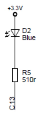
From this image, it is clear that when the PC13 pin is LOW, the LED will be turned ON and when the PC13 pin is HIGH, the LED will be turned OFF. Hence, in the code, I will using the same configuration to turn ON and OFF the LED.
Code
The code for the project is given below. It is very simple and if you already implemented an Arduino HC-05 Bluetooth Module interface, then the code is very easy to understand.
const int LEDPin = PC13;
char inputData = 0;
void setup()
{
Serial1.begin(9600);
Serial1.println(“Electronics Hub”);
Serial1.println(“HC-05 Bluetooth with STM32”);
pinMode(LEDPin, OUTPUT);
}
void loop()
{
if(Serial1.available() > 0)
{
inputData = Serial1.read();
if(inputData == ‘0’)
{
digitalWrite(LEDPin, HIGH);
Serial1.println(“LED is turned OFF”);
}
else if(inputData == ‘1’)
{
digitalWrite(LEDPin, LOW);
Serial1.println(“LED is turned ON”);
}
}
}
Serial1 in the above indicates that I am using UART1 for communication. You can also use UART2 or UART3 of STM32F103C8T6, provided you make the appropriate connections and give proper initialization in the code.
Working
The working of the project is very simple. First, upload the program to the STM32 Blue Pill and then make the connections as per the circuit diagram. Then go to the Bluetooth Settings on your Android Smart Phone and pair the HC-05 Bluetooth Module.
When pairing for the first time, it will ask for a pin. In that case enter 1234 or 0000. In my case it is 1234. Once the pairing is done, open your Bluetooth terminal App on your Android phone and search for Bluetooth devices. Select the HC-05 Bluetooth Module.
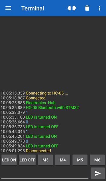
Now, configure the App to transmit ‘1’ and ‘0’. When ‘1’ is transmitted, the LED will be turned ON and when ‘0’ is transmitted, the LED will be turned OFF.
Conclusion
In this project, I have talked about one of the commonly used Communication Modules by beginners and hobbyists i.e. the HC-05 Bluetooth Module. Also, I have demonstrated a simple project by Interfacing HC-05 Bluetooth with STM32F103C8T6 Blue Pill Board.
A simple Bluetooth terminal App on an Android Smart Phone is used to communicate with HC-05 Bluetooth Module to transmit some data. The STM32 will then decode the data and turn the on-board LED ON or OFF.

One Response
SOUNDBOX Device Blue Tooth always on problem
Hi, I need advice please,
Wish to disconnect the Bluetooth Circuit so it cannot send or accept wireless transmission without damaging other operations the board may be doing, such as the Charge control…as I cannot control its BT-On BT-Off operation,
Wish to only be able to connect the speaker through the present 3.5mm connector (wired only) and continue being able to charge through the USB PC connector from Speaker.
Reason: Voice communication security with BT always On.