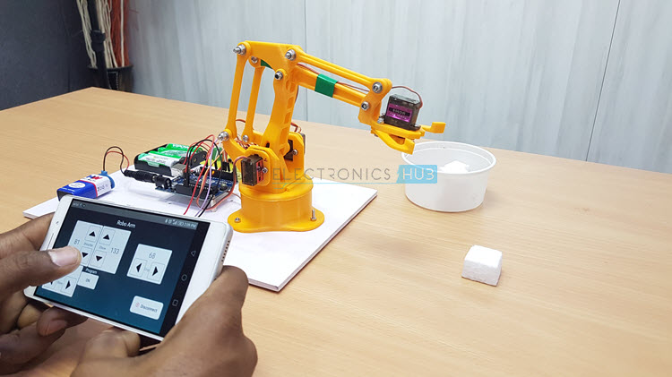
In this project, I’ll show you how to build an Arduino & Bluetooth Controlled Robotic Arm using Android Phone. This Robotic Arm can be operated in either manual mode or can be programmable to be operated in Fully Automatic Mode.
You have already seen one Robotic Arm project from Electronics Hub, which we did everything from scrap (except for the motors and Arduino). We got very good response from you guys for that project and based on that we decided to make a better version of it, Version 2.0, if I must say.
Before reading further, try this SIMPLE ROBOTIC ARM USING ARDUINO.
DIY Arduino & Bluetooth Controlled Robotic Arm Project
This DIY Arduino & Bluetooth Robotic Arm Project is operated using an Android Phone over Bluetooth Communication. We have developed an Application for Android Phones, using which you can control the Robotic Arm for manual operation or program it for fully automatic operation. I’ll explain them in the later sections.
Circuit Diagram of Arduino & Bluetooth Controlled Robotic Arm
Let us start with the circuit diagram of the Arduino & Bluetooth Controlled Robotic Arm Project. The following image shows the circuit diagram with all the necessary connections.
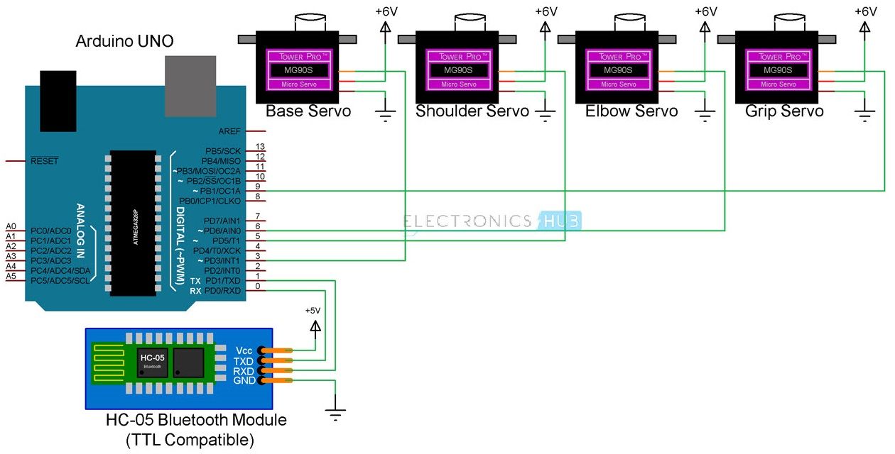
The circuit diagram seems very simple but the construction part of the Robotic Arm is a little bit complicated.
Components Required for Robotic Arm Project
- Arduino UNO [Buy Here]
- 4 x Tower Pro MG90S Metal Gear Servo Motors
- HC-05 Bluetooth Module
- 3D Printed Robotic Arm Parts with necessary screws, nuts and bolts
- Proper power supply for Arduino and 4 Servo Motors
- Connecting Wires
- Android Phone with custom application installed
Component Description
Arduino UNO and Bluetooth Module are pretty straight forward in the list of components but the interesting components are the Metal Gear Servos and the 3D Printed Robotic Arm parts.
Metal Gear Servo MG90S
The Servos used in the Robotic Arm construction are TowerPro MG90S Metal Gear Micro Servos. We have chosen this particular servo because the regular plastic gear servos were not stable and also the stall torque is less.
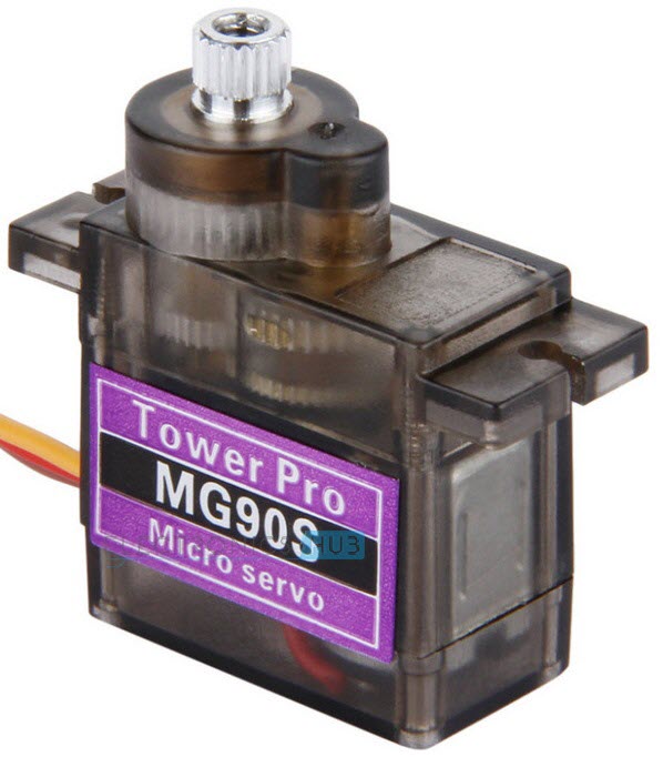
At 6.6V supply, this metal gear servo provides a stall torque of 2.2Kg/CM (which is considerably more than that of the regular SG90 Servo).
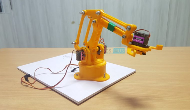
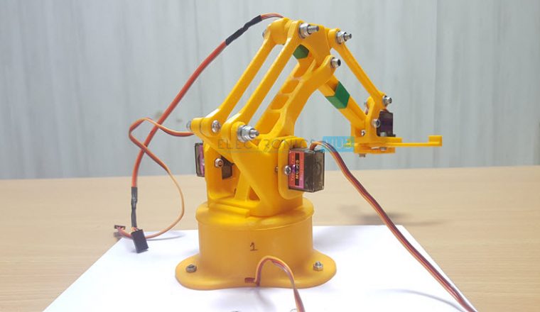
3D Printed Robotic Arm
One of the important feature of any Robotic Arm project is the aesthetics. So, we decided to go for 3D Printed Parts for the Robotic Arm. daGHIZmo designed a 3D Robotic Arm called EEZYbotARM and uploaded the files in Thingiverse website.
For 3D Model files of the Robotic Arm, please visit this link.
Based on those 3D model files, we made the parts using a local 3D Printer outlet. The quality is very good and the dimensions are also very close to the real object (not accurate).

If you observe the above image, I have designated the parts of the Robotic Arm as Base, Shoulder, Elbow and Grip. Subsequently, the servo motors are also named Base Servo, Shoulder Servo, Elbow Servo and Grip Servo.
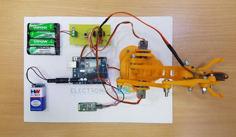
Circuit Design
As mentioned earlier, the design of the circuit is very simple. The Control Signals of the 4 Servo Motors are connected to 4 PWM Pins of the Arduino UNO as follows: Base Servo – Pin 3, Shoulder Servo – Pin 5, Elbow Servo – Pin 6 and Grip Servo – Pin 9 of Arduino respectively.
All the servo motors are given a 6V power supply while the Arduino UNO is given with a 9V supply. The TX and RX of the HC-05 Bluetooth Module are connected to the RX0 and TX0 pins of the Arduino i.e. Pins 0 and 1.
NOTE: Do not connect the Bluetooth Module while programming the Arduino.
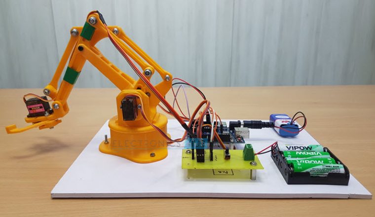
Assembling the 3D Printed Robotic Arm Parts
If I explain the step-by-step assembly procedure of the 3D Parts of the Robotic Arm, it will be a very lengthy and boring read. So, I’ll post some pictures of the completed robot and will make a separate video on how to assemble the Robotic Arm. In the meantime, take a look at these images.

Android App for Arduino & Bluetooth Controlled Robotic Arm
Instead of using Potentiometers or serial communication through computer, we have decided to take a step further and design a simple Application for Android Phones in order to control the robotic arm.
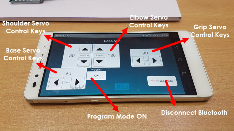
The following image shows the app layout in a smart phone running Android version 6.0. But the App is tested for Android version 8.0 and is working fine.
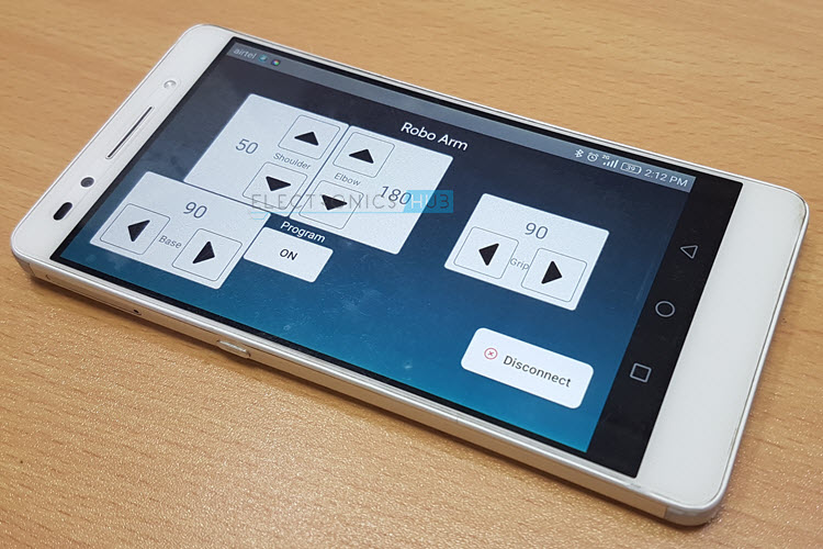
There are four pairs of Arrow Control Keys each pair for Shoulder, Elbow, Base and Grip Servos respectively. There is a Program button, using which, you can enable the program mode. More about this in the working of the project.
NOTE:
- This app uses the Android Phone’s Bluetooth function. This app is not available in Google Play Store right now as it is still being tested.
- As of now, we haven’t developed an App for iOS.
Working of the Arduino & Bluetooth Controlled Robotic Arm
A simple, 3D Printed, Android Phone based, Arduino & Bluetooth Controlled Robotic Arm is designed and developed in this project. We will now see the operation and working of this Robotic Arm.
Install the Application in your Android Phone and provide necessary permissions to access the device’s Bluetooth. If the Bluetooth Module (HC-05) is not paired with the mobile, pair it using the Bluetooth Settings of the Phone.
Once the device is paired, open the App and it will automatically list out the paired Bluetooth devices. Select the correct Bluetooth Module and if everything goes well, you will enter into the main control panel.
Here, you can see controls for the four servo motors of the Robotic Arm i.e. Base, Shoulder, Elbow and Grip. Use the arrow keys of the respective Servo motor and control the robotic arm. This part of the working is the Manual Operation of the Robotic Arm, where every movement must be manually adjusted.
Next comes the interesting part. You can see a button in the center called “Program”. At any time of the operation, if you press this button, the Robotic Arm will RESET (moves to a default position) and the Programming Mode is activated.
In this mode, you can program the Robotic Arm to perform a series of tasks in an automatic fashion. For example, if you want to pick small objects from one place and place it in another place, you do not have to manually adjust the values all the time.
All you need to do is to enter in to programming mode and teach the Robotic Arm to follow a series of steps to achieve the task. Once you program the Robotic Arm you can run the program and it will loop those programmed steps until stopped.
You can also pause the automatic operation anytime and resume from the same point. Also, if you wish to come out of the programming mode and operate the Robotic Arm manually, you can simple “OFF” the Programming Mode.
It will be difficult to clearly explain the operation of the Robotic Arm (in manual and automatic mode) here. So, I’ll make a video for the same.
Highlights of Arduino & Bluetooth Controlled Robotic Arm Project
- This Robotic Arm can be controlled using any Android based Smart Phone with Bluetooth.
- Dedicated App for Android Phone to control the Robotic Arm.
- There are two modes of operation: Manual Mode and Automatic Mode.
- For regular or manual operation, you can control the Robotic Arm by manipulating the values of individual servo motors of the Robotic Arm.
- When Programming Mode is enabled, you can program your Robotic Arm for fully automatic operation.
- The Robotic Arm contains four Metal Gear Servos and 3D Printed Parts for the structure.

25 Responses
This project is tested?
Yes. Perfectly working. We will upload the video soon.
Where are the codes ? Can you show them ,
please.
can’t we use microcontroller for this project?
what is the name of the application ?
which anroid app is use here can u tell me????
code programation Arduino and Bluetooth Controlled Programmable Robotic Arm
can you share in here the code of apk ?
Thanks a lot !!
so interesting. can you please share the other layer of a PCB ( PCB tracks)
Can you share the dimensions of the 3d printed arm
cost
Did u use cinematic calculos at the program??
Hallo ravi,,
how to make an app like that. can you divide the app from the beginning until it can be used
What is the price please?
Total cost of this project?
Hey, can you please share your code and the application you used? Thanks, I would really appreciate that
what is the total cost of this project? i need this. How can i get ths project from Banglades.
can you please send the code please !!!!!!
your project is to good even i would wanna try this thank you
hello
can you please tell me the exact name of the android app?
i to need the name of the app or the way to develop one
can i know about the dimensions of the robot which is 3D printed. And can u give me the name of the app.Will there be any differences when we use the raspberry-pi instead of the arduino. Bro i don’t have any websites this is related to my project which is similar to this one.
Regarding the Arm, you can find all the details of the 3D Model in the following link:
https://www.thingiverse.com/thing:1015238
Coming to the app, it is a custom made app, specific to this project. It is slightly buggy, so we haven’t made it public (yet).
can u just give me the name please. its urgent
where can i get the pcb? can u name the pcb which u have used?
If i use wifi module can give me the code with the same matériel : 3 or 4servo motors and arduino uno , thnk you very much you did great job