In this project, I’ll show how to design a Digital Voltmeter using 8051 Microcontroller and also explain its working. Voltmeter is a measuring instrument, used to measure the voltage difference between two points in electrical network. Generally, there are two types of voltmeters – one is analog voltmeter and the other one is digital voltmeter.
In analog voltmeter a pointer moves on the scale to represent the voltage. Digital voltmeter directly displays the voltage in digits with the help of analog to digital converter. This article explains you how to design a digital voltmeter in two methods 1) using 8051 microcontroller and 2)the other using IC L7017.
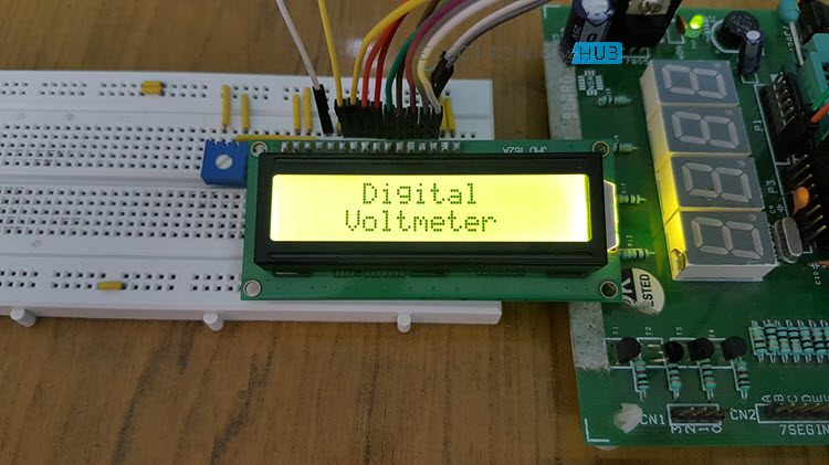
Digital Voltmeter using 8051 Microcontroller
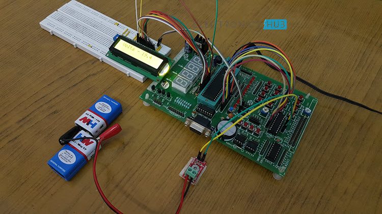
This project measures the input voltage from 0V to 25V. Here, the input voltage should be DC voltage to get the accurate output on LCD. If you apply AC voltage as input, then will see the continuous running numbers on LCD as AC varies continuously.
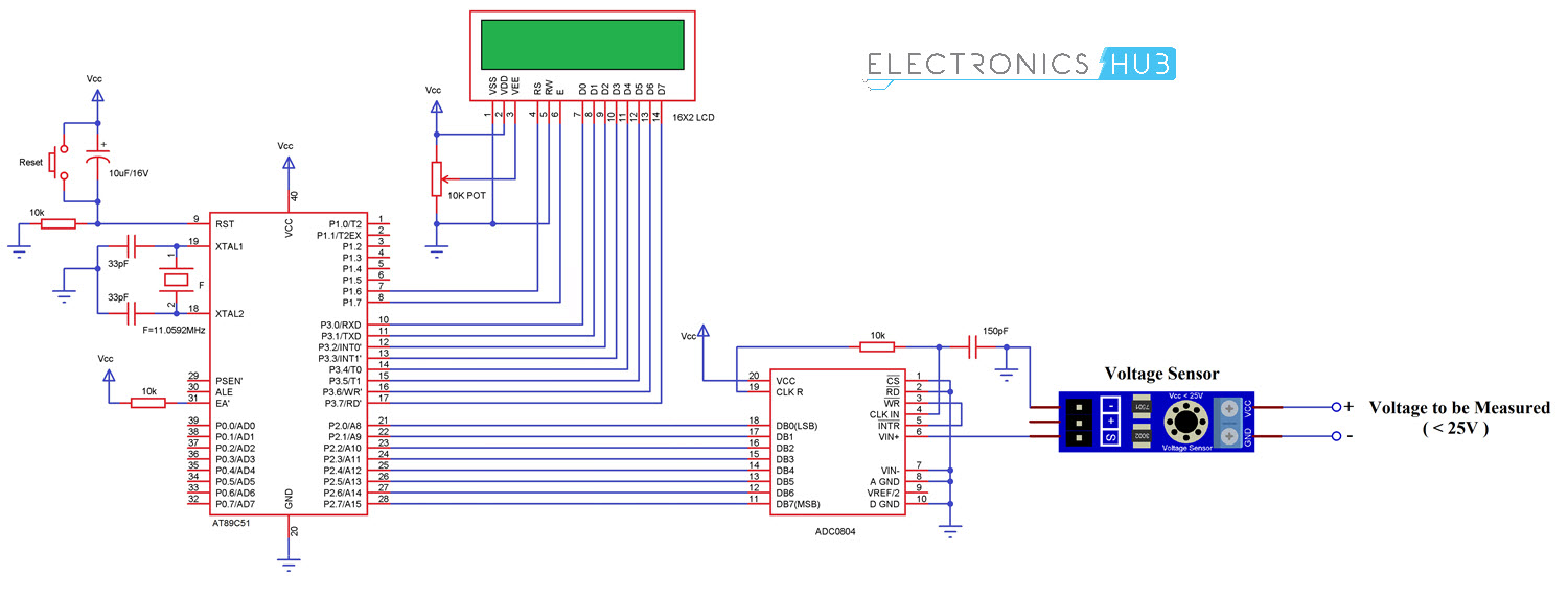
The major components in this project are 8051 microcontroller, a Voltage Sensor Module and an ADC IC ADC0804. In this project, we use analog to digital conversion process to display the voltage.
Also read the related post: How to Interface 16×2 LCD with 8051 Microcontroller?
Analog to Digital Conversion
In real world, mostly we find analog data. To manipulate this data using digital systems, we need to convert analog data to digital, so that microprocessor or microcontroller is able understand and manipulate the data.
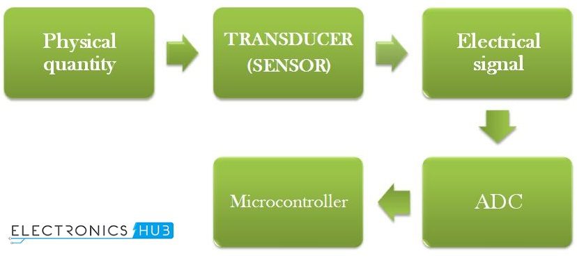
- Transducer: Transducer or sensor is used to convert the physical quantity to electrical energy. Light dependent resistor, temperature sensor, humidity sensor, gas sensor etc. are examples of transducers.
- ADC (Analog to Digital Converter): ADC converts the input electrical voltage to Digital value.
- Digital System: this system reads input digital data and displays the physical quantity on LCD for understanding purpose.
Here ADC IC generates the output digital value based on the input electrical voltage. The 8051 microcontroller reads this digital value and displays it on LCD.
Digital Voltmeter using 8051 Microcontroller Circuit Diagram
- AT89C51 micro controller
- ADC0804 IC
- 25V Voltage Sensor
- AT89C51 programming board
- Variable resistor (to demonstrate the program)
- DC Adapter or Battery
Digital Voltmeter Circuit Design using 8051 Microcontroller
In the above circuit, analog to digital converter IC data bits are connected to the PORT2. LCD data pins are connected to the POTR3 of controller and control pins RS and EN are connected to the P1.6 and P1.7 respectively.
ADC0804
This is an 8 bit analog to digital converter. This IC uses successive approximation method to convert analog values to digital. It can take only one analog data as input. The step size of this IC is varied by varying the reference voltage at pin9. If this pin is not connected, VCC will be the reference voltage.
For every 19.53mV, rise in input voltage the output is incremented by 1 value when the step size is at 5V. The conversion time of this IC depends on clock source.
ADC Features
- 0 to 5V analog input voltage.
- Built in clock generator.
- Differential analog inputs.
- Adjustable reference voltage.
Below table shows the different step sizes for different reference voltages.
In the above circuit diagram, pin9 (Vref/2) is left open so that input voltage span can be 0 to 5V.
Step size = Vref/(2 pow(n))
Where n is resolution. For ADC0804 the resolution n=8. The digital output can be calculated using the formulae
Dout = Vin/stepsize.
Vin – analog input voltage
For example, let the analog input voltage is 4V, then the digital output is Dout=4/19.53mV=204.
Steps to Convert the Analog Input to Digital
- Read the ADC value from the PORT2.
#define dat P2
val=dat*0.02;
- After multiplying by 100, you get a positive interger value of three digits.
val1=val*100;
- Separate individual numbers and print them on LCD including the decimal point.
temp=(((val1/100)%10)+48);
display(temp);
display(‘.’);
temp=(((val1/10)%10)+48);
display(temp);
temp=((val1%10)+48);
display(temp);
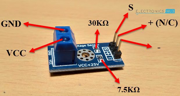
Voltage Sensor
The voltage sensor module is a simple voltage divider network that increases the analog input range of the ADC to about 25V.
Code
How Digital Voltmeter Circuit Works using 8051 Microcontroller?
- Initially burn the program to the at89c51 microcontroller.
- Now give the connections as per the circuit diagram.
- Connect a battery or any voltage source at the input of the voltage sensor.
- Make sure that maximum analog input voltage should be less than 25V DC
- Connect a digital multi meter at the Input terminals of the voltage sensor.
- Now switch on the board supply.
- Now observe both LCD and digital multi meter, both displays the same voltage (or very similar voltages).
- If possible, try to slowly vary the analog input voltage. Now you can observe that both multimeter and LCD displays the same voltages so that we can say that voltmeter is working properly.
- Switch off the board supply.
Digital Voltmeter Circuit Applications
- This system is used to measure the voltage in low voltage applications.
- Used to measure the toy batteries.
- We can measure the physical quantities like temperature, humidity, gas etc. using this system with a little modification.
Digital Voltmeter Circuit Limitations
- The input analog voltage range should be 0 to 5V.
- Using this system we can measure only one analog input value at a time.
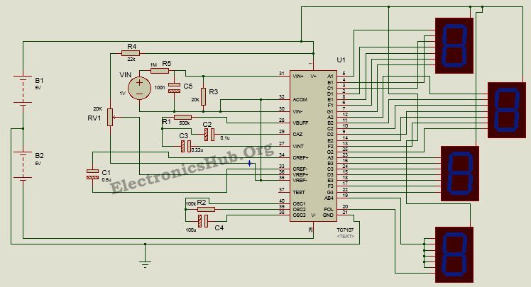
Digital Voltmeter Circuit using ICL7107
Voltmeter can also be designed without using any microcontroller.Here is the circuit of voltmeter using L7017 IC
Here we design a analog to digital converter working as a digital voltmeter using a low power three and half digit A/D converter ICL7107 having internal 7 segment decoders, display drivers, a reference and a clock.
An advantage is this IC can directly drive non multiplexed seven segment display without any external decoding circuitry. The circuit can measure voltage in the range of 200mV to 2V with an interval of 0.001V.
Principle Behind the Circuit
This circuit is based on the principle of using ICL7107 as an analog to digital converter. The whole operation is divided into two phases- Analog to digital conversion and decoding.
Analog to digital conversion is done using the process of integrating and reference integrating. In other words, the input signal is first integrated to bring the output of integrator to ramp signal and an opposite polarity reference voltage is then integrated to bring the output of integrator back to zero.
The resultant digital code obtained is then decoded using to display decoders to drive the display unit.
Digital Voltmeter Circuit Diagram using ICL7107
How Design Digital Voltmeter Circuit?
Designing the circuit requires appropriate selection of the components as given below:
- Selection of Oscillation Circuit Components: For a typical oscillating frequency of 48 KHz, the oscillating resistor has been chosen to be about 100K and the capacitor about 100pF.
- Reference Capacitor: The value of reference capacitor is chosen to be between 0.1uF and 1uF. Here we choose a 0.5uF electrolyte capacitor.
- Auto-zero Capacitor: The auto zero capacitor is selected such that its value is between 0.01uF and 1uF. Here we select a 0.1uF capacitor.
- Integrating Capacitor: The integrating capacitor forms an essential part of the integrating circuit. Its value is determined by the integration period t, optimum integration current I and integrated voltage Vint. For a time period of 83mSec, current of 4uA and voltage of 2V, the value of capacitor is found to be around 0.16uF. Here select a 0.22uF capacitor.
- Integrating Resistor: The value of this resistor is given by the full scale analog input voltage and the optimum integration current. We select a resistor of 500K for a full scale input voltage of 2V.
How to Operate Digital Voltmeter Circuit?
The IC is powered by a dual supply of +/- 5V. Once the circuit is powered, the reference signal is set by adjusting the reference resistor. The reference voltage needs to be about half of the input voltage. The oscillating components – resistor and capacitor determine the oscillating or clock frequency of the device.
The reference capacitor is charged to the reference voltage. A feedback loop is then closed to charge the auto zero capacitor such that is compensates for any fluctuations in voltages. Later the converter integrates the differential voltage at the input for a fixed time such that output of the integrator is a ramp signal.
A known reference voltage is then applied to the input of integrator and is allowed to ramp till the output of integrator becomes zero. The time taken for the output to return back to zero is proportional to the input signal and the digital reading is given as:
Display Count = (Vin/Vref)*1000.
The next process involves decoding the digital count to produce a seven segment compatible signal so as to drive the displays. The digital output is then displayed on the multiplexed 7-segment display.
Applications of Digital Voltmeter Circuit
- This circuit can be used in digital multimeters to provide digital reading of measured voltage.
- It can be used to measure AC and DC voltages.
- It can be used to measure physical quantities like pressure, temperature, stress using transducer circuit and signal conditioning circuit.
- It can be used in applications where high accuracy and high resolution is required.
Limitations of Digital Voltmeter Circuit
- It can measure voltages only up to a low range.
- The IC used is a CMOS device and is highly static.
- Difference in reference voltage for negative and positive input voltage can cause rollover error, i.e. a common mode error.
- Using a full scale negative input voltage of 2V can sometimes cause output of the integrator to saturate.
- Internal heating from the LED drivers can cause degradation in performance.
- Reference temperature coefficient, internal chip dissipation and package thermal resistance tend to increase the noise level.

34 Responses
hi its nice post i red it good wish you all the best and i got some good research with mcu 80c51 i ll send for you
thanks
best regard
gayan.
good
Sir, Please send the code of this project. I am an electrical engineering student performing the same project.
Hi
we have our project on Digital Voltmeter using 8051 allocated by our Professor, So, we just want to replicate this project so, if you send us code it will be really helpful here’s my email id: engr.umarsajjad@gmail.com
slam
i have assigned digital voltmeter using 8051 mini project.can u plzz send me it’s code.here is my email id
norinfatima8@gmail.com
1) we are students in comsats .we have to submit this project in our final asessment.
2) we liked this project and our supervisor also liked it and asiigned us this project,so we have decided to make same project.
3)we are making dig voltmeter using 8051 u-controller as described above.
Please go through the article for project code
if you send me the code it will be really helpful here’s my email id: tiago_af_santos@hotmail.com
thanks sir alot but i need the whole to perform this same project on breadboard………
Hello!
I need this project code to get familiar with it. its also part of my project.. My project will be different as i m designing multi-meter.
Project code is already Uploaded..U can go through it
can you help me to make multimeter…it will be very helpful for me!
Sir, Please send the code of this project. I am an electronics engineering student making the same project.
Sir, Please send the code of this project. I am an electronics engineering student making the same project.
Send me the project code
Hello i am electronics engineering student. I am doing same project Please send me project code.
I need code for this project. please!!
I am doing same project. At the time of simulation i got errors in project code. So I need correct code.
Code is tested.There is no error in the code.Let us know the error you are getting in simulation so that we can help you..
I perform this project in my acdamic year.i need the code.
Code is present in the article.Download it from there..
in article showing to codes. it will be grateful if u send me the hex code @ prasannajethi@gmail.com.
please send me project code….
please mail or reply the project code. the one that is mentioned on the website is not opening on my pc,
if you can, plese mail or reply the word /notepad/hex file.
I need its code. I can try makining project.
Makining the code.
i need the assembly code for digital voltmeter with 8051.
so please send me the assembly language for this
What is the 18 and 19 pin
xtal1 and 2
12M. Crystal between the capacitors
Adc = adc_avrg *59
Is this the adc’s mathematical equation ??? Or why we multiply it by 59 ???
Sir please send me the code for Digital voltmeter using 8051 things I am an electronic student and I have been prepared for making this project as mini projects
hi can i know how u converted hexadecimal back to voltage while displaying in lcd
and can i know how to transmit that voltage in UART for displaying in pc or someother device.
Thank u
please do reply ASAP.
is it possible to make an ammeter in the same way .. .?
You have given two program files.How do I make them into a single Hex file
Can u give the algorithm