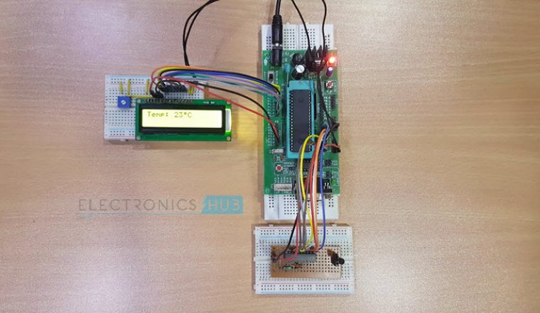
This project demonstrates the design, development and operation of the Celsius scale Thermometer using LM35 Temperature Sensor and AT89C51 Microcontroller. The circuit contains the analog temperature sensor LM35, which has the advantage of providing an output directly proportional to the Celsius Temperature, without having the need to be calibrated.
The project also consists of the 8 – bit Analog to Digital Converter ADC0804, which uses the successive approximation conversion technique. The ADC0804 is controlled by the microcontroller, which processes its output to display the resultant temperature reading on an LCD display. This article gives details about the microcontroller program, circuit design and the circuit operation.
Celsius Scale Thermometer using AT89C51 and LM35
Before going to know about this circuit, get an idea about Digital Temperature Sensor.
Construction and Output Video
Principle behind the Circuit
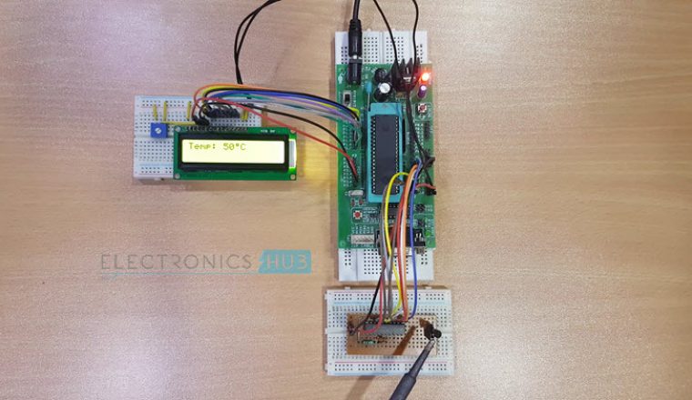
The circuit works on the principle of Analog to Digital conversion. The temperature is sensed by an analog temperature sensor (LM35) and this analog value is converted in to a digital value using an ADC (ADC0804). A microcontroller (AT89C51) then processes the digital signal to display the temperature reading in Celsius on the display screen (16×2 LCD).
Also Read the Post: Thermistor Temperature Sensing Alarm Circuit
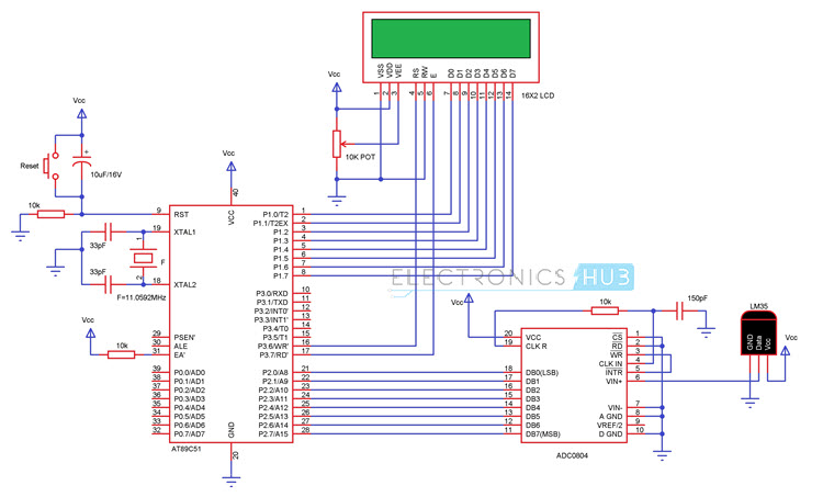
Circuit Diagram of Celsius Scale Thermometer
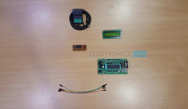
Components Required
- 8051 Microcontroller (AT89C51)
- 8051 Development Board
- 8051 Programmer
- 16 x 2 LCD Display
- 10KΩ Potentiometer
- ADC0804 – ADC IC
- 10KΩ Resistor (1/4 Watt)
- 150pF Capacitor (Ceramic Disc Type) – Code: 151
- LM35 – Temperature Sensor
- Connecting Wires
- Power Supply
- Keil µVision IDE
- Willar Software
- You may need the following components if you do not have an 8051 Development board
- 11.0592 MHz Quartz Crystal
- 2 x 33pF Capacitor
- 2 x 10KΩ Resistor (1/4 Watt)
- 10µF Capacitor (Polarized)
- Push Button
Celsius Scale Thermometer Circuit Design
Designing the circuit mostly involves designing the microcontroller circuit, interfacing the ADC, LM35 and LCD to the microcontroller AT89C51.
Microcontroller Circuit Design
Oscillator Circuit: The oscillator circuit consists of a crystal oscillator with oscillation frequency of 11.0592 MHz and two ceramic capacitors, each of 33pF, to ensure stability.
Reset Circuit: The reset circuit is designed using a push button, a 10KΩ resistor and an electrolyte capacitor of 10µF to ensure a reset pulse width of 100ms and a reset voltage of 1.2V.
EA Pin: Since we are not using any external memory, EA Pin is pulled high using a 10KΩ Resistor.
Interfacing ADC and LM35
LM35 Temperature Sensor IC and ADC0804 ADC IC form the input part of the circuit. LM35 consists of three pins: GND, VOUT and VS. VOUT of LM35 is connected to Analog In Pin VIN (+) of the ADC0804 IC (Pin 6).
Pin 20 (VCC) of ADC0804 is connected to +5V supply. Pins 1, 2, 7, 8 and 10 (CS’, RD’, VIN (-), AGND and GND) of ADC0804 are connected to GND. A 10KΩ Resistor is connected between the clock pins CLKR and CLKIN (Pins 19 and 4) of ADC0804. A 150pF Ceramic Capacitor is connected between CLKIN (Pin 4) and GND. Pins 3 and 5 i.e. WR’ and INTR’ are connected together.
The eight data out pins DB0 – DB7 (Pins 11 to 18) of ADC0804 are connected to PORT2 Pins of the 8051 Microcontroller.
Interfacing LCD
The RS, RW and EN pins are connected to port pins P3.6, GND and P3.7 respectively. The data pins are connected to PORT1 of the microcontroller.
Working of Celsius Scale Thermometer Circuit
The ambient temperature is sensed by LM35 temperature sensor which produces an output voltage that is proportional to the temperature at a rate of 10mV per degree Celsius. This analog voltage is fed to the Analog to Digital Converter (ADC0804), which is an 8 – bit ADC working on the principle of successive approximation conversion.
The Analog to Digital Converter ADC0804 is configured to continuously read the input Analog signals and also continuously produces the Digital Output at its Digital Out Pins. In order to make the ADC0804 to continuously read the Analog Input values, we need to tie the INTR’ pin and WR’ pin together. Also, to continuously make the digital data available at the Digital Out pins of the ADC0804, CS’ and RD’ pins must be pulled low.
The Analog to Digital Converter, continuously takes the analog signal from LM35 and converts it in to digital values. The digital output of the ADC0804 is in the form of 8 – bit binary data and these are also continuously available.
8051 Microcontroller takes this digital data and performs a simple mathematical calculation. This calculation will convert the received digital data from the ADC0804 to Temperature in Degree Celsius.
Now, the microcontroller will send this data to the LCD and display it. Since the ADC is continuously reading the Analog Data from the LM35 Temperature Sensor and sending it to the Microcontroller through the Digital Pins, the temperature will be updated at all times and the same is displayed on the LCD.
Are you interested to get some more project circuits? Then visit electronics mini projects
Algorithm Steps to Write Circuit code for Celsius Scale Thermometer
The following algorithm needs to be followed to write the code in C language.
- Read the data from ADC0804.
- A small calculation is performed on this received data.
- Initialize the LCD by sending proper commands.
- Send data to the LCD containing the temperature reading
Applications of Celsius Scale Thermometer Circuit
- It can be used at mobile places like cars to keep a track of the temperature.
- It can be used to control the switching of loads like motors, heaters based upon the temperature.
- It can also be used at homes to get the temperature reading.
Limitations of the Circuit
- It requires additional analog to digital conversion.
- This circuit can only measure values in Celsius.

5 Responses
Want some body to develop a mini Two digit timer & temperature controller with flexible key pad switches
Once check the following 2 links:
https://www.electronicshub.org/temperature-controlled-dc-fan-using-microcontroller/
https://www.electronicshub.org/2-digit-up-down-counter/
i want prog for this ckt
Could you give me the code please?
I want the codes for this project.