Temperature sensors are widely used in electronic equipment to display the temperature. You can see the digital clock displaying the room temperature value. It is due to the temperature sensor embedded in it. In this project, I will show you how to design a Digital Temperature Sensor Circuit. In the process, I will explain two circuits: one using 8051 Microcontroller and the other using ATmega8 Microcontroller.
The temperature value is analog. Hence, it is converted to digital value using an Analog-to-Digital Converter (ADC) and then it is displayed. This article describes the same, converting analog value to a digital value.
Digital Temperature Sensor Circuit Principle
The main principle of this circuit is to take the analog temperature values, convert them into digital values and display the digital temperature value om LCD or 7-Segment Display.
Here, 8051 and ATmega8 microcontrollers are used. The ATmega8 has inbuilt analog to digital converter with six multiplexed channels of 10-bit resolution. This reduces interfacing of external analog to digital converter IC. The analog temperature value is directly applied to input ADC channels of microcontroller. Successive approximation method is used for Analog to digital conversion internally.
But in case of 8051 Microcontroller (AT89C51 is used in this project), it doesn’t have any built-in ADC like ATmega8. Hence, I am going to interface an external ADC IC ADC0804 with 8051 Microcontroller to convert the Analog temperature values to digital values.
Related Post: Celsius Scale Thermometer using AT89C51 Microcontroller
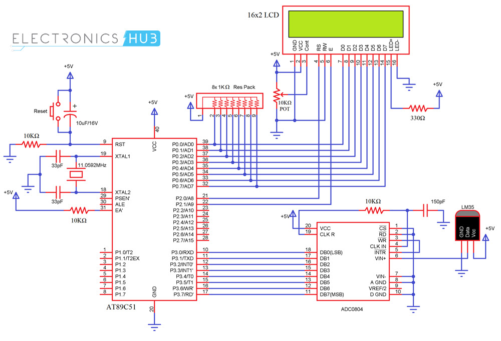
Digital Temperature Sensor Circuit using 8051
Circuit Diagram
Components Required
- AT89C51 (8051 Microcontroller)
- 11.0592 MHz Cystal
- 2 X 33pF Capacitor
- 10μF/16V Capacitor
- 3 X 10KΩ Resistor
- 1KΩ x 8 Resistor Pack
- 10KΩ POT
- 16X2 LCD Display
- ADC0804
- LM35
- 150pF Capacitor
- 330Ω Resistor
- Power Supply
- Connecting Wires
- 8051 Programmer
Circuit Design
The digital out pins of the ADC IC are connected to PORT3 Pins of 8051. PORT0 pins are pulled-up using 1KΩ Resistor pack and they are connected to the data pins of 16×2 LCD. P2.0 and P2.1 of 8051 are connected to RS and E of LCD.
LM35 is connected to Analog In pin VIN+ (Pin 6) of ADC0804. Essential components like oscillator, reset etc. are not explained here.
Code
Working
After making all the connections and burning the code onto the 8051 Microcontroller, turn ON the power supply. The LM35 Temperature Sensor provides the Analog Temperature Data to ADC0804, which it converts into Digital Values and sends to 8051.
Upon receiving the digital values, the 8051 Microcontroller performs a small calculation and then displays the temperature on the LCD.
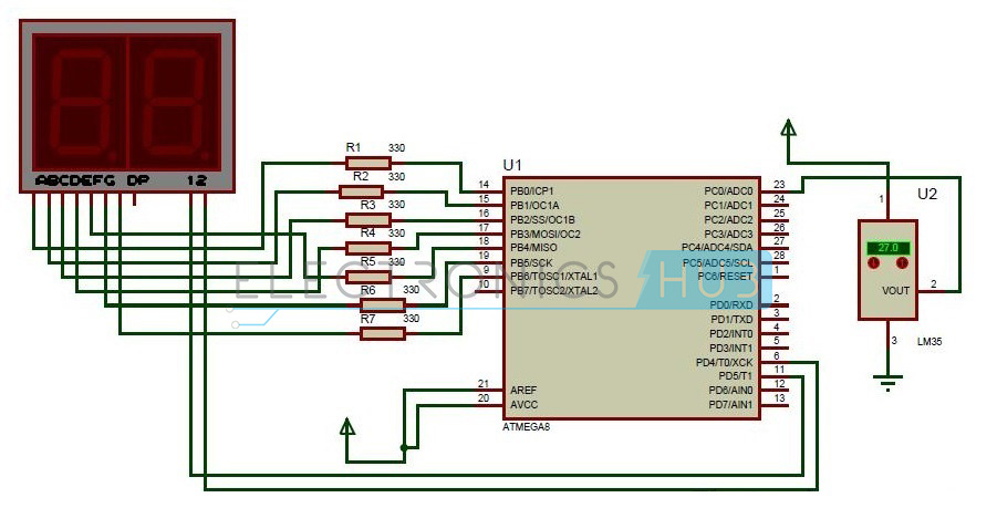
Digital Temperature Sensor Circuit using ATmega8
Circuit Diagram
- Resistors – R1 to R7 having the value of 330 Ohms each.
- LM35 Temperature sensor
- ATmega8 Microcontroller
- 7 Segment Display
Digital Temperature Sensor Circuit Design
The digital temperature circuit consists of ATmega8 microcontroller, LM35 temperature sensor, 7 segment display. The temperature sensor Lm35 is connected to one of the ADC channels of microcontroller.
ATmega8 has six ADC channels at Port C. PC0-PC5 pins of Atmega8 act as ADC channels. This shows that one can interface six analog values. But only one conversion is done at a time depending on the priority of the input channels. The resolution of ADC is 10 bit. Remember that for conversion Vref and Avcc are externally connected as shown in circuit.
Generally, all the port pins of ATmega8 microcontroller act as normal input /output pins until their special functions are declared. ADC registers inside the controller have to be declared in order make Port C to act as ADC channel.
Lm35 temperature sensor has three terminals. Placing the flat surface towards you first pin is Vcc, Second pin is Output and the third pin is Ground. Output pin of temperature sensor is connected to the first ADC channel i.e. PC0 pin of microcontroller.
Seven segment display has eight pins and one common pin. Leaving Dp, connect all the seven pins to port B. Connect A to PB0, B to PB1,_____, G to PB6. Seven segment display used here is common cathode display. Current limiting resistors were used between controller and the display.
Digital Temperature Sensor Circuit Simulation Video
How to Operate Digital Temperature Sensor Circuit?
Initially power the circuit. The micro controller continuously checks for input at ADC channel. It converts the analog temperature to digital value and is displayed on the seven segments. Increment or decrement the temperature value by clicking on the arrow marks below the display in temperature sensor. Whenever there is a change, the ADC channel converts the input and displays on the seven segment. The temperature value displayed is twice the original value .This is because of variations in the step size. So, before displaying the value divide the value by 2 and subtract 1 from it to display accurate value.
Algorithm for Programming to Microcontroller
The following steps explain you to set the internal ADC registers of ATmega8 microcontroller and displaying value on seven segment display.
- Initially select one channel from six ADC channels to which temperature sensor is connected and select source for reference voltage using ADMUX register.
Ex: ADMUX=01000000.
If ADC0 is the channel selected and Avcc with external capacitor at Aref pin is selected
- Enable ADC and select prescalar value using ADCSRA register.
Ex: ADCSRA = (1<<ADEN)|(1<<ADPS0)|(1<<ADPS1)|(1<<ADPS2)
If prescalar value of 128 is selected and enabling ADC. ADPS0, ADPS1, ADPS2, ADPS3 are pre scalar bits.
- Check for the flag bit in ADCSRA register which sets after completion of the conversion.
- Read the value from ADC register and assign value to port B which displays on seven segments.
- The two digit value obtained can be displayed on two seven segments.
Digital Temperature Sensor Project Output Video
Applications of Digital Temperature Sensor Circuit
- The digital temperature sensors are widely used in day-to-day life
- They are used in environmental applications.
- Digital temperature sensors can be found in air conditioners where it adjusts the temperature according to the room temperature.
- They can be seen in digital clocks displaying room temperature along with time.
- It can be used in dash boards in the car to display temperature of the engine, to avoid stopping suddenly due to overheat.
- No need of external ADC IC for conversion in case of ATmega8.

8 Responses
which software is used for designed of circuit
nurul says:
The Software for simulation is “Proteus 8” I guess….
The Download of which is free
But the Licensing may cost…maybe…
sir please can you send us the program which is used here in this circuit for generating hex file please
What is the code used to simulate this circuit ?
May I get the code please ?
I really need it ASAP
Can you please give the code for the circuit
sir please send the code..its really urgent..Thanks
Sir Can u send me the coding used in this circuit