An LC meter circuit is used to measure value of a reactive element like a capacitor or an inductor. This article describes the design and functioning of a simple circuit using a 555 Timer and a microcontroller. An advantage of this circuit is its simplicity and accuracy.
LC Meter Circuit Working Principle:
The LC meter circuit is based on the basic principle of measuring capacitance (inductance) using the relation between capacitance (inductance) and voltage. A potential divider is arranged using a resistor and a capacitor (inductor) such that an input AC voltage across the divider results in an output voltage across the capacitor (inductor). This voltage is fed to the control pin of a 555 Timer IC in astable mode such the frequency of output signal is proportional to the control voltage. This signal in form of pulses is fed to a microcontroller which calculates the frequency and then the capacitor (inductor) value is calculated.
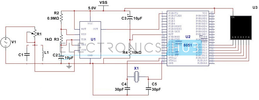
LC Meter Circuit Diagram:
LC Meter Circuit Design:
This is a simple circuit and does not require much complexity in designing. The first step of the design involves designing the 555 Timer circuit. A potential divider circuit is designed using a resistor and capacitor (inductance) such that voltage across the capacitor (inductor) is equal to half of the input peak to peak voltage of 8V. This voltage is fed as control voltage to 555 Timer. Since relation between the output frequency and control voltage requires the term ln(1-(Vcontrol/(Vcc-Vcontrol)) (as per Spehro Pefhany equation), the control voltage should be less than the supply voltage for 555 Timer (which is 5V). Assuming the time period of a duty cycle of 60% and an output signal of 1msec, the time high value is 0.6msec. Value of time low signal is around 0.4msec. Since this value is equal to R3C1, selecting a value of 1k for the resistor, value of capacitor, C1 is around 0.6uF. Assume the selected values and substituting required values in the given equation:-
Th = C1(R2+R3)ln(1-(Vcontrol/(2Vcc-Vcontrol))
We get R2 to be around 0.9MOhms.
Since for the potential divider circuit, voltage across the reactance is half the input voltage, the value of resistor is equal to the reactance. In other words based upon our choice of resistor R1, we can determine the capacitance (inductance) range. Here we select a pot of 100k; capacitance range can be up to 3.18nF, inductance range is up to 3.18H.
The second step involves designing the microcontroller circuit. Here we are using 89C51 microcontroller. It involves designing the reset circuit and oscillator circuit. Since voltage at reset pin should be at a threshold value of 1.2V and reset pulse width should be about 100ms, we select the values of resistor and capacitor such that RC >=100ms. Here we select a 10K resistor and a 10uF electrolyte capacitor. Designing the oscillator circuit involves selecting a crystal oscillator to provide a clock signal of 24MHz. Two ceramic capacitors of each 30pF are connected to two ends of the capacitor to ensure smooth operation. The crystal is connected to pins 18 and 19 of the microcontroller. Apart from designing the reset circuit, another part of microcontroller circuit design involves designing the interfacing circuit. This is done by using a single digit 7 segment display connected to port P2.
Do you know How to Design a Digital Voltmeter Circuit using 8051 Microcontroller?
How LC Meter Circuit Works?
Circuit operation can be best explained in two phases. In the first phase an input AC voltage of 8V peak would produce a voltage of 4V across the reactive element under measurement. This voltage is fed to the control pin of the 555 Timer. This ensures a control voltage is applied to inverting terminal of the upper comparator. As capacitor charges through the resistors R2 and R3, a voltage is developed across the capacitor. As soon as the capacitor voltage is greater than the control voltage, upper comparator output is a logic high signal, causing the flip-flop to reset. This causes the 555 output to be a high signal. As the transistor connected internally to the discharge pin saturates, the capacitor starts discharging. As soon as this voltage is less than 1/3Vcc, lower comparator output is a logic high signal. This causes the flip flop to set and output of 555 Timer is low. Thus a oscillating signal is produced at the output. Since the sooner the capacitor voltage reaches the control voltage, sooner logic high level is reached at the timer output, the width of the output pulse depends upon the control voltage.
In other words an output signal is produced whose frequency depends upon the control voltage. This signal is fed to the microcontroller.
The second phase of operation involves the functioning of microcontroller. As soon as the device is powered, the compiler scans the port pin P1.0. As per the program, compiler checks the time for which the output signal is high. This is the time high value of signal. Since this value depends upon the control voltage, the compiler calculates the control voltage. Since this control voltage is the voltage across the element under measurement, the capacitance or inductance value is calculated. Since this value is in decimal form, the compiler converts this value into a hexadecimal value. This value is sent to port P2 which is connected to 7-segment display.
LC Meter Circuit Limitations:
- This circuit calculates only the reactance value and not the phase difference.
- The capacitance/inductance range is limited and for higher capacitance.

3 Responses
Hi my name is kamaldeepsingh i m doing engineering 4th sem . i dont know about coding so i just know about .is microcontroller needs coding or not..
yup it sure does,,,,,
hello
thank you for your helpful tutorial
I have a question! what is final formula for calculation of C and L ?