A Voltmeter or a Voltage Meter is a measuring instrument that is used for measuring voltage or potential difference between two points in a circuit. Voltmeters are an important piece of equipment which are associated with any kind of electronics project. They are used in measurement of both AC and DC voltages.
Voltmeters are again classified in to two types namely Analog Voltmeter and Digital Voltmeter. Analog Voltmeter consists of pointer that moves across a scale and the movement is proportional to the voltage measured.
Analog Voltmeters are further classified based on their principle of construction. Some of the commonly known analog voltmeters are Permanent Magnet Moving Coil Voltmeter, Rectifier Type Voltmeter, Electrostatic Type Voltmeter, Moving Iron Type Voltmeter etc.
Analog Voltmeters generally have an error percentage of 5% and the parallax error is often an issue. But analog voltmeters can be used to measure ranging from few volts to several thousand volts.
To overcome the defects of analog voltmeters, Digital Voltmeters are introduced. Unlike analog voltmeters, which scale and a pointer to show the measured voltage, digital voltmeters directly display the measured voltage numerical on a digital display.
The percentage of error in digital voltmeters is usually less than 1% and the accuracy can be increased in precision digital voltmeters with high speed measurement and option of storing the values in a memory.
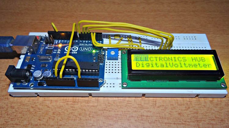
In this project, an Arduino based Digital Voltmeter which can measure voltages up to 50V is designed.
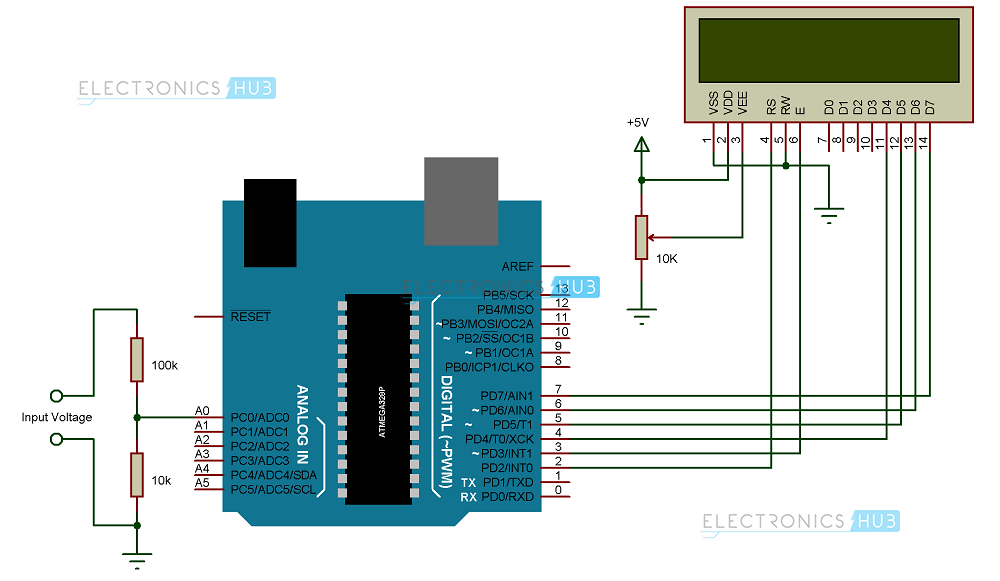
Digital Arduino Voltmeter Circuit Diagram

Components
Component Description
Arduino UNO
Arduino UNO is one of the most popular electronics prototyping board based on ATmega328P Microcontroller. ATmega328P is an AVR architecture based 8-bit microcontroller.
16 x 2 LCD Display
A 16 x 2 LCD display is the most commonly used display unit for microcontroller based applications.
It supports 16 characters in a row with two such rows. It also supports special characters and even custom characters.
Circuit Design
For measuring voltages less than or equal to 5V, first circuit can be used. For measuring voltages up to 50V, second circuit can be used. The LCD part in both the circuits are same.
Pin 1 and 2 (Vss and Vdd) of the LCD power supply pins for display. They are connected to ground and +5V supply respectively. Pin 3 (Vee) of the LCD is the contrast adjust pin of the display. It is connected to the wiper terminal of the 10KΩ POT while the other terminals of the POT are connected to +5V supply and ground respectively.
The next three pins of the LCD are control pins. Pins 4 and 6 (RS and E) of the LCD are connected to digital input/output pins 2 and 3 of Arduino respectively. Pin 5 (RW) of the LCD is connected to ground.
The next connections are with respect to data pins. The LCD is used in 4-bit data mode and hence data pins D4 to D7 are used. Connect pins 11 to 14 (D4 to D7) of the LCD are connected to digital input/output pins 4 to 7 of the Arduino. Pins 15 and 16 are the supply pins of the backlight LEDs. Pin 15 (LED+) of the LCD is connected to +5V supply through a current limiting resistor of 220Ω. Pin 16 (LED-) of the LCD is connected to ground.
In the first circuit, which is used to measure voltages up to 5V, there are no additional connections and the voltage to be measured is connected directly to the analog input A0 of the Arduino UNO.
In the second circuit, which is used to measure voltages up to 50V, we need to connect a voltage circuit additionally. The output of the voltage divider circuit consisting of 100KΩ resistor and 10KΩ resistor is connected to the analog input pin A0 of the Arduino UNO with other end of the 100KΩ resistor connected to the voltage to be measured and the other end of the 10KΩ resistor connected to the ground.
The ground terminal of the input voltage to be measured and Arduino UNO must be common.
Working
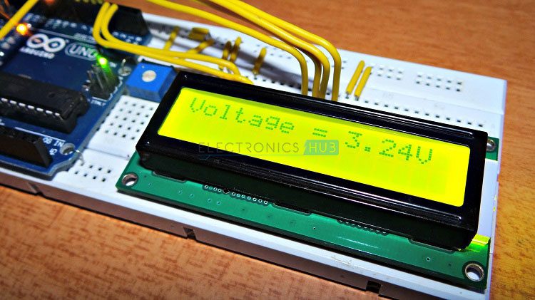
The aim of the project is to build a digital voltmeter using Arduino UNO. The components required and the construction of the project is very simple. The working of the project is explained here.
In a digital voltmeter, the voltages to be measured, which are in analog form, are converted to digital form with the help of Analog to Digital Converters (ADC). Hence, the ADC feature of the Arduino UNO is utilized in this project.
In the first circuit, which is used to measure a maximum voltage of 5V, the input voltage is given to the analog input pin of the Arduino. The reference voltage of the ADC is 5V. The ADC in Arduino UNO is of 10-bit resolution. Hence, the input voltage is calculated by multiplying the analog value at the analog pin with 5 and dividing the value with 210 i.e. 1024.
The range of voltages for Arduino UNOs analog input is 0V to 5V. Hence, in order to increase this range, a voltage divider circuit must be used.
In the second circuit, the range of the analog input of Arduino UNO is increased up to 50V by using a voltage divider consisting of 100KΩ resistor and 10KΩ resistor. With the help of the voltage divider circuit, the input voltage being measured is brought down to the range of Arduino UNOs analog input.
The rest of the calculations are made in the programming part of the Arduino UNO.
NOTE
- The disadvantage of using voltage divider based voltmeter is the error of measurement. Hence, we need multiple ranges of voltmeter.
- In order to reduce the error, the ratio of R1 and R2 in the voltage divider must be minimum.
- For example, to measure an input voltage of 50V, the ratio of R1 and R2 must be greater than ((50/5) – 1) i.e.
R1/R2 > ((50/5) – 1)
R1/R2 > 9
Hence, if we choose R1 as 100KΩ and R2 as 10KΩ, then it is possible to measure the voltages up to 50V.
Applications
- An Arduino based Digital Voltmeter is designed in this project which can be used to measure different ranges of DC voltages.
- The circuit can be extended to measure even AC voltages with slight modification in circuit and code.

4 Responses
Excellent job
Thank you. Very instructive project. My only comment centres on the use of the ‘temp’ variable in Code 1. I puzzled over this a bit and realised that this was used to correct for voltages measured using the voltage divider circuit.
It might be more helpful to transpose the two blocks of code, so that Code 1 refers to the circuit in Figure 1, etc.. At present, in order to make the circuit in Figure 2 work correctly, you need to use Code 1 – not Code 2 – and vice-versa
Y two codes
how to take input voltage during simulation in proteus?