In this ESP8266 WiFi Module based project, we will see about a Web Controlled Servo using ESP8266 where the position of the Servo Motor can be controlled through a Web Page (within the same WiFi Network).
Overview
Servo Motors are one of the most commonly used motors in both industries and DIY Projects. Two of the most famous project involving Servo Motors are our ARDUINO ROBOTIC ARM and DIY BLUETOOTH CONTROLLED 3D PRINTED ROBOTIC ARM.
So, in this project, I’ll demonstrate a Servo Motor based project involving Tower Pro SG90 Servo Motor and ESP8266 WiFi Module.
I’ll be creating a simple Web Page (HTML) with a slider. When this web page is accessed from a computer or mobile phone that is connected to the same WiFi Network as the ESP8266, you can control the position of the Servo Motor by adjusting the slider.
Concept behind Web Controlled Servo using ESP8266
Normally, in order to control a Servo Motor with Arduino (for example), all you need is a Servo Motor, Arduino and a Potentiometer. Depending on the position of the POT, the PWM value of the Servo Motor input changes and consequently the position of the Servo Motor’s shaft changes.
In case of a Web Controlled Servo Motor using ESP8266, Arduino still drives the Servo Motor but the input isn’t from a POT but a Web Page we created.
The slider in the web page sends the angle values and is received by the ESP8266, which acts as a Web Server. The ESP8266, upon receiving the value, transmits it to the Arduino, which then changes the position of the Servo Motor according to the value.
One important thing to remember here is that both the Server and client should be on the same network i.e. the ESP8266, which acts as the Server, and the Computer (or a Mobile Phone), which is the client, must be connected to the same WiFi network.
Prerequisites for Web Controlled Servo using ESP8266
First and important thing is that the ESP8266 Module must be flashed with AT Commands Firmware. For more information on this, please refer HOW TO FLASH UPDATE AT COMMANDS FIRMWARE IN ESP8266.
Second important thing is to control the ESP8266 (that is loaded with AT Commands Firmware) using Arduino. For this project, please refer WIFI CONTROLLED LED USING ESP8266 AND ARDUINO.
Circuit Diagram
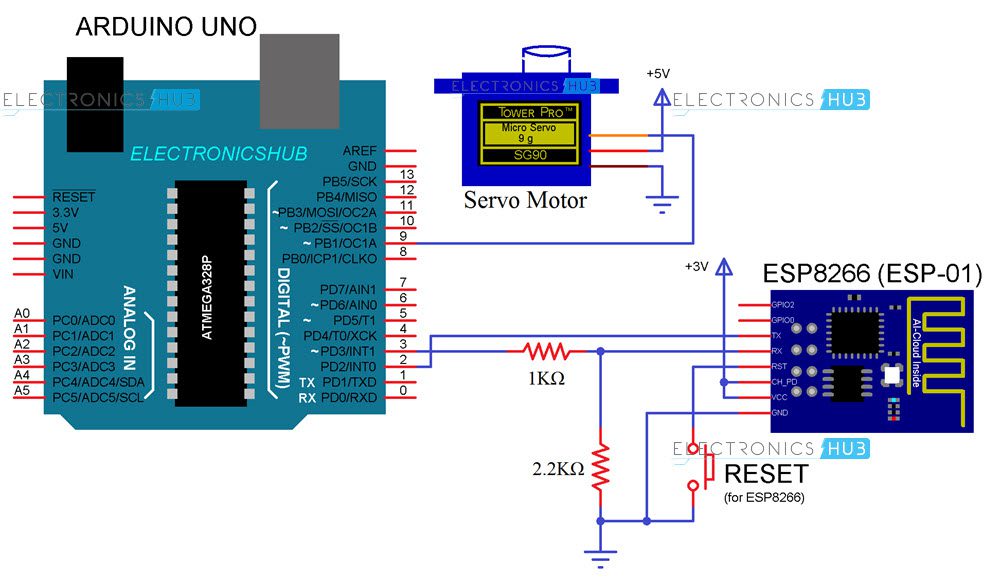
The circuit diagram for Web Controlled Servo using ESP8266 WiFi Module is given in the image below.
Components Required
- Arduino Board (any Arduino)
- ESP8266 based Board (I’ve used ESP-01)
- Tower Pro SG90 Servo Motor
- Jumper Wires
- Resistors (1 KΩ and 2.2 KΩ) – both are ¼ Watt
- Button
- Slide Switch (SPDT)
- Computer (or Mobile Phone)
Design of the Circuit
The main program will be for Arduino and it will be responsible for everything i.e. connecting ESP8266 to WIFI, getting information for ESP8266 and finally controlling the Servo.
In order to enable Serial Communication between Arduino and ESP8266, Pin 2 and 3 of Arduino are enabled as Software Serial (in the program). Here, Pin 2 acts as RX and Pin 3 as TX. So, connect TX of ESP8266 to Pin 2 of Arduino and RX of ESP8266 to Pin 3.
Since, ESP8266 cannot tolerate 5V, the TX of Arduino (pin 3) is first level shifted using two resistors (1 KΩ and 2.2 KΩ) and then connected to RX of ESP8266.
The VCC, CH_PD and GND pins of ESP8266 are connected to 3.3V, 3.3V and GND respectively. The RESET pin of ESP is connected to a button where the other end of the button is connected to GND.
Pin 9 of Arduino will provide the necessary PWM signal to the Servo (Orange). Its other pins are power supply pins and are connected to 5V and GND (Red and Brown).
Code
Arduino Code
The Arduino Code for the Web Controlled Servo using ESP8266 project is given below.
HTML Code for Web Page
In order to create a simple Web Page, I’ve used the following HTML Code.
NOTE: In order to create a Web Page using this HTML Code, save this code with an extension .html in a folder and in the same folder place the “myjquery,js” file which you can download from here.
Working of Web Controlled Servo using ESP8266
Let us now see the working of the Web Controlled Servo using ESP8266 and Arduino. After making all the connections as per the circuit diagram, upload the Arduino code to Arduino UNO.
After the code is uploaded, if you open the serial monitor, you can see the status of the ESP8266 WiFi Module.
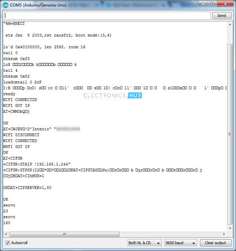
After all the initialization steps are done (set mode to Station mode, connect ESP to WiFi, set static IP and start web server), you can proceed for Web Control.
Now, open the HTML file using any web browser. A simple text indicating the project will be displayed. Below that, you can see a slider.
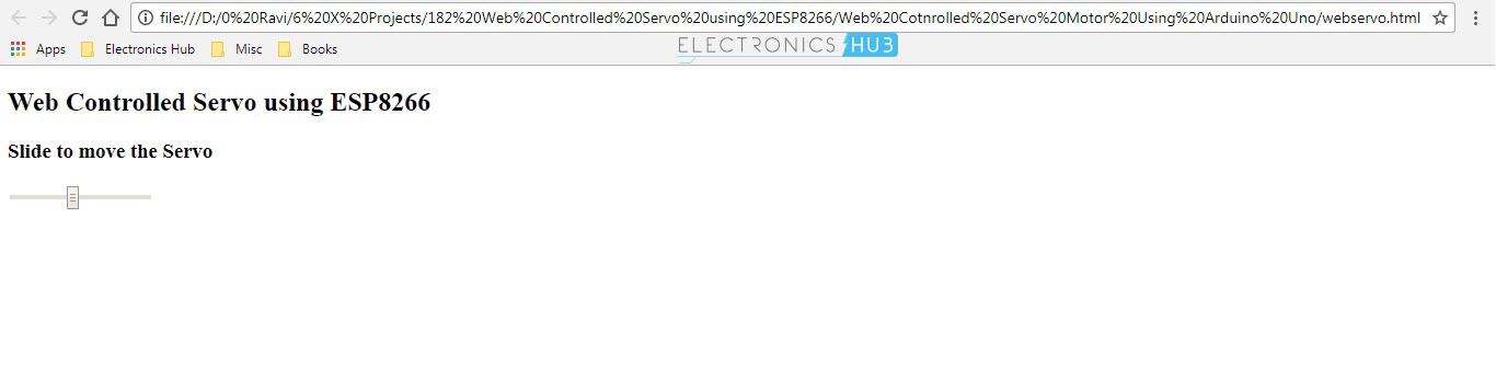
If everything is right, when you change the position of the slider, the position of the servo Motor will be changed.
Applications
The idea behind Web Controlled Servo using ESP8266 is to implement a web-controlled device (in this case, a Servo Motor) i.e. to control a motor through internet.
This application can be further extended to more advanced and complex projects like controlling a Robot from the Internet.

2 Responses
very nice
You can do all of this with just the esp8266 and servo, you don;t need the Arduino.