In this tutorial, we will learn how to control a Servo Motor using ESP32 Development Board. To demonstrate the working of ESP32 Servo Control, we will first make a Sweep application where the servo oscillates back and forth. Then we will see how to control the Servo using a Potentiometer. Finally, since ESP32 is all about of IoT Development, we will implement a Web Controlled Servo using ESP32 Project.

I already made a Web Controlled Servo using ESP8266. If you are interested in that, check it out.
NOTE: The Web Controlled Servo using ESP8266 was an early implementation. If you want to have a latest design (as implemented in this project), you can follow similar steps and apply it to ESP8266 NodeMCU board as well.[ESP32 Projects for Beginners]
Prerequisites
There isn’t much needed before proceeding but there are two earlier ESP32 Projects, which will be help in implementing this ESP32 Servo Control Project easily. The first one is the ESP32 PWM Tutorial and the second one is the ESP32 Web Server Tutorial.
Instead of using a library for Servo Motor Control, I will use the ESP32’s PWM Peripheral to control the Servo. So, it is good to understand how to generate PWM Signals in ESP32 using the LEDC Peripheral.
The next requirement is very simple. If you want to build an ESP32 based Web Controlled Servo Project, then you have to build a Web Page and configure ESP32 as a Web Server to host that web page. Having knowledge on how to create an ESP32 Web Server will be very useful.
So, complete those projects before proceeding further.
A Brief Note on Servo Motors
Servo Motors are used everywhere: Robotics, Industries, Automation, CNC Machines and even DIY Projects. Since we are interested in small and affordable servo motors for use in our projects, let us talk about two of the commonly used Servo Motors: SG90 and MG 996R.
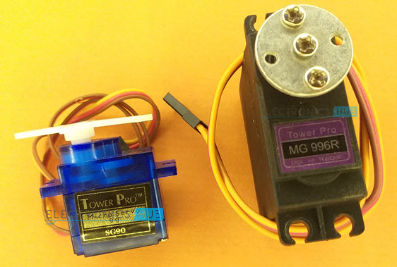
Both these Servo Motors are cheap and are easily available everywhere. The SG90 is a plastic gear Servo with a torque of 1.8 kgf.cm while the MG 996R is a metal gear Servo with a torque of 9.4 kgf.cm.
If you take a look at the data sheet of these servos, the SG90 has a rotation angle of 1800 while the MG 996R has only 1200 rotation.
An important point to take from the datasheets is that the Control Signal of both these servos is a PWM Signal with a period of 20ms (50 Hz) and the pulse duration has to be between 1ms to 2ms.
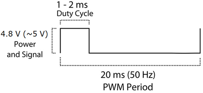
When the pulse duration is 1.5ms, the Servo is in ‘middle’ position. If a 1ms pulse is applied, the servo moves all the way to left while a 2ms pulse will make the servo move all the way to right.
NOTE: I will use the SG90 Servo Motors in all the projects as it is more commonly available and used.
ESP32 Servo Control
As mentioned earlier, instead of using “Servo” libraries, we will be using the LEDC PWM Controller to set the control signal of the Servo. The beautiful thing about LEDC PWM Controller is that you have complete control on the parameters of PWM Signal Generation i.e., frequency, resolution and duty cycle.
The frequency of the PWM Signal, which must comply with the specifications of the Servo Motor, is set at 50 Hz. A standard 8-bit resolution is used. The important part is setting the duty cycle.
Duty Cycle of the PWM Signal determines the position of the Servo and it ranges between 1ms for extreme left, 2ms for extreme right and 1.5ms for center positions.
Since duty cycle is often represented as percentage, we will continue to use the same. So, when I set the duty cycle as 50, it means 50% duty cycle.
Components Required
- ESP32 DevKit Development Board
- Servo Motor
- 10 KΩ Potentiometer
- Breadboard
- Connecting Wires
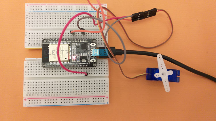
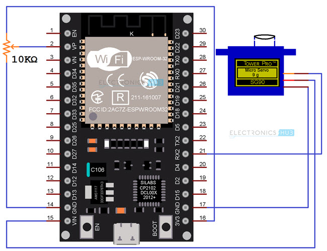
Circuit Diagram
The following image shows the connections between ESP32 and Servo Motor. The operating voltage of SG90 and MG 996R Servo Motors is 4.8V. So, connect the VCC (Red) wire to VIN of ESP32. VIN is the input from the USB. So, it will be around 5V. Connect the GND (Brown) wire to one of the GND pins of ESP32.
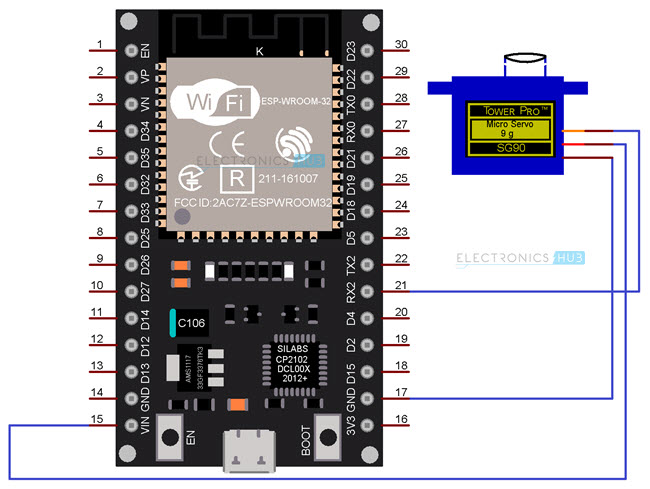
Finally, the PWM Control Wire (Orange). Connect this wire to any of the PWM Pin of ESP32. Since, there are no dedicated PWM Pins on ESP32 and essentially you can configure any GPIO Pin as a PWM Pin, I connected the Control Wire of Servo to GPIO 16 (marked as RX2 on the board).
Controlling Servo Motor using Serial
In the first project, let us see how to control the servo motor by entering the ‘Duty cycle’ values from the Serial Input. This project is just to figure out the extreme values of ‘Duty cycle’ for complete rotation of the Servo.
Code
In my case, the extreme values of duty cycle are 5 for extreme left and 32 for extreme right. These are the limits of duty cycle which I must follow for extreme positions. These values might be different for you as each Servo is different.
So, to find out the limits, upload the code to ESP32 after making the connections, open the serial monitor, enter different duty cycle values to test and note the extremes.
ESP32 Servo Sweep
Using the above duty cycle limits, we can write a Servo Sweep program, which will oscillate between the extreme left and right positions continuously. Here is the code for that.
Code
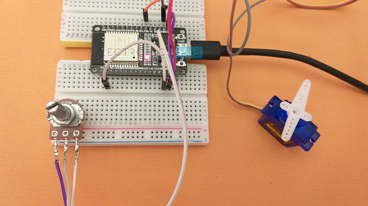
Adjust Position of Servo using POT
Another useful project is to precisely adjust the position of the Servo Motor using a Potentiometer. A 10 KΩ Potentiometer is connected to an ADC Pin of ESP32. I used the ADC1_CH0, which is marked as VP on the Development Board.
The digital values from the output of ADC, which will be in the range of 0 – 4095 (as it is a 12-bit ADC) are mapped to extremes of the duty cycle (5 and 32).
Circuit Diagram
Code
ESP32 Web Controlled Servo
The final project for ESP32 Servo Control is the Web Controlled Servo. The process for creating the web server with a web page is same as what we saw in the ESP32 Web Server tutorial.
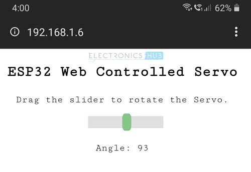
In order to control the position of the Servo, I opted for a Slider to be displayed on the web page. Since the SG90 Servo can be positioned between 00 and 1800, adjusting the slider sets out the angle of the servo and its range is, well, 0 to 180.
When we change the position of the slider, the server receives a ‘GET’ request along with the desired angle embedded in the request. We have to decode the angle from this request and map the angle to the previously measured duty cycle values (5 and 32).
Code
I commented all the important bits of the code. Modify the code as per your requirement (CSS Styling, Slider, Servo Duty Cycle range etc.). Also, change the SSID and Password in the code (lines 5 and 6).
The following image a screen shot of the ESP32’s Web Controlled Servo web page accessed using Chrome browser on a laptop.
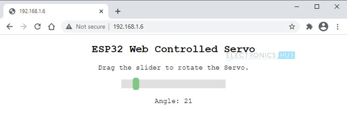
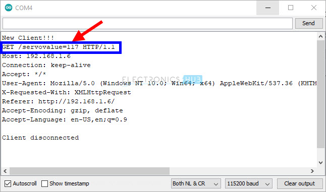
Whenever we change the position of the slider, the ESP32 Web Server receives a request and the following image is a screen shot of the serial monitor displaying the request.
You can also access the web page on mobile as long as both ESP32 and the mobile phone are connected to the same Wi-Fi network. The following image is a screenshot of web page accessed on a mobile phone.
Conclusion
A complete tutorial on controlling Servo Motors using ESP32 Development Board. You learned how ESP32 Servo Control works, how to calculate the duty cycle of Servo’s PWM Signal, different ways to control a servo: Serial Input, Sweep, using Potentiometer and finally, a complete application on Web Controlled Servo using ESP32.

One Response
great tutorial ,
but I do still need an internet connection for the https://code.jquery.com/jquery-3.6.0.min.js\
Is there a work around for this?