Robotic Arm is one of the popular concepts in the robotic community. Robotic arms are very common in industries where they are mainly used in assembly lines in manufacturing plants.
The first thought for a beginner would be constructing a Robotic Arm is a complicated process and involves complex programming. Even our thoughts were same in the beginning and once we put our full focus on the thing, we found it rather easy and all it takes is some time and tinkering.
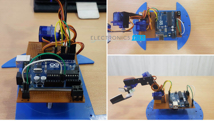
In this project, we have built a simple Robotic Arm, which is fully automated to do certain tasks. Apart from the Microcontroller (we have used Arduino UNO) and servo motors, all other components that are part of the arm were collected from office scrap (mostly).
This is to say that we can build a Robotic Arm with the things we got around and do not require pre designed parts or 3D printed parts.
How To Build A Simple Arduino Robotic ARM [DIY]
We will see a step by step construction of the Robotic Arm. The construction made in this project and demonstrated in this blog is as per our convenience and just to give an idea to the reader. You do not have to follow the exact same steps, if you are planning to build one.
First, we will see the circuit diagram for the project. The following image shows the necessary circuit for the robotic arm. The circuit is actually very simple and involves only Arduino and 4 servos. But the construction is more complex compared to the actual circuit itself.
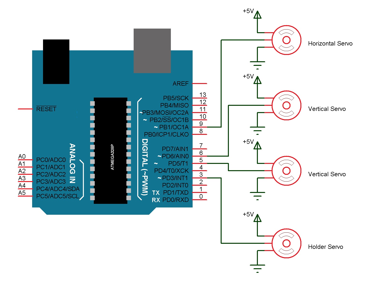
NOTE: The power supply to the servos should not be given from Arduino. A separate 5V regulated supply must be used.
The control pins of each servo must be connected to the PWM pins of the Arduino. We will be making an automated robotic arm and hence we don’t require any potentiometers. Now that we have seen the simple circuit diagram, we will jump to the actual construction.
Output Video
Construction
Step 1
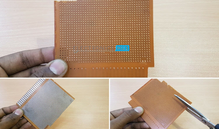
- Take a zero board of approximately 11 CM x 7CM dimension. We will use this board to make some electrical connections and also fix the Arduino board and second vertical servo.
- Cut the unwanted parts from the board and shape is as per the dimensions mentioned above.
Step 2
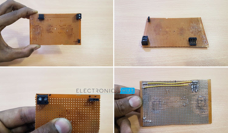
- Now we need to connect the terminals for power and servo control signal. For this, we will use a 2 – pin screw terminal, 2 – pin female header pins and set of male and female header pins. The connectors are placed with enough room for Arduino to be placed.
- The electrical connections i.e. 5V connection and GND connection are soldered behind the board.
- Make sure that the soldering is done carefully and there are no short circuits.
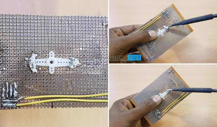
Step 3
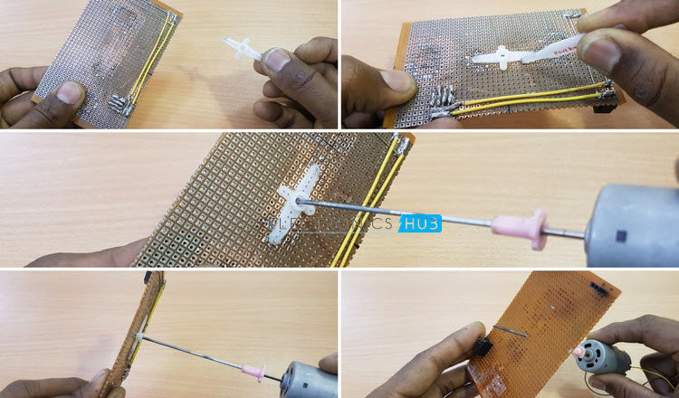
- Glue the servo horn to the backside of the board, right at the center. This horn will be later connected to the horizontal servo.
- The servo horn has a hole for it to be fixed to a servo motor. But we need to drill a hole through the board to screw the servo to the board.
- We have used a high torque motor we found in an old printer in order to drill the hole.
Step 4
- For the servo horn to be fixed firmly to the board, we soldered some lead to the board over the arms of servo horn.
- This step is just precautionary measure to ensure that the servo horn won’t be floating in air after screwing.
- This step completes the board part of the project. From the next step onwards, we will start constructing the main Arm part of the robot.
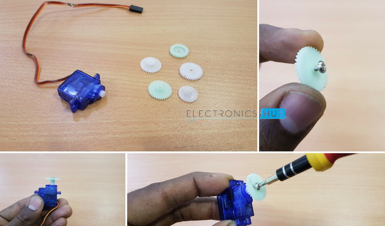
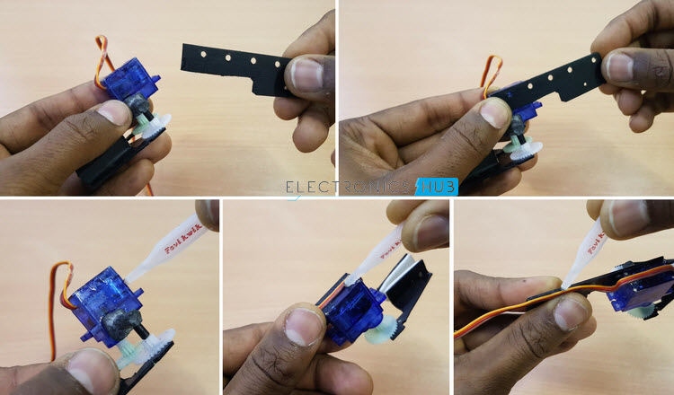
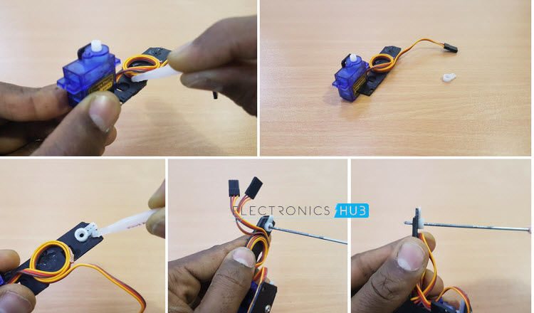
Step 5
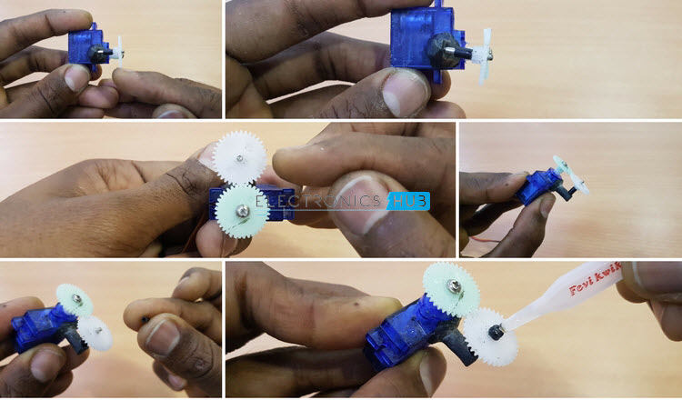
- First, we will start with the holder servo, the servo that actually holds the objects. For this, we will use some gears.
- Select two similar gears with equal teeth count and screw one gear to the output spline of the servo. Ensure that the gear is screwed firmly to the servo.
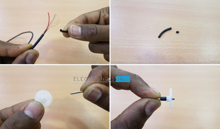
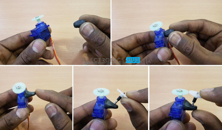
Step 6
- Now take the second gear and insert a tiny metal rod into the gear. This gear acts as a counter rotating wheel for the holder servo.
- Take a small piece of the rubber sleeve of a wire and insert it to the rod. This sleeve will hold gear in place without wobbling.
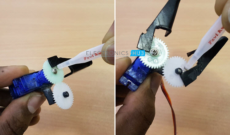
Step 7
- The two gears must be attached together at their teeth so that when one gear rotates in clockwise direction, the other rotates in anti-clockwise direction.
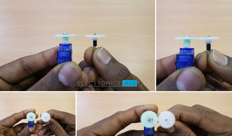
Step 8
- In order to attach the gears, we need to hold the second gear firmly to the servo. For this, we used epoxy compound.
- Equal amount of resin and hardener must be taken and mix them thoroughly until it results in a complete black colored compound. [Check this article: Best Resin 3D Printer]
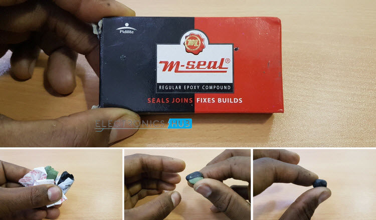
Step 9
- The compound is attached to the servo and it is mold into a convenient shape.
- Insert the second gear’s rod in to the compound and adjust the height so that the second gear is at same height as the main gear.
Step 10
- Now, make sure that the teeth of both the gears are aligned. After aligning the gears, allow the compound to dry for some time.
- Scrap of the unnecessary compound from the servo to reduce the weight.
- Glue a small rubber sleeve at the top of the second gear to hold it firmly.
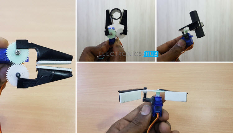
Step 11
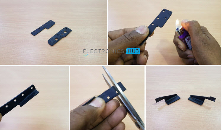
- In this step, we will construct the object holding parts. Two plastic pieces from an old toy were taken for this purpose.
- Slightly heat the plastic and bend one end as shown. This structure can be easy to hold different object.
- Cut off any extra lengthy and unnecessary pieces from the plastic. Make a similar piece from the other plastic piece but this one is a mirror image of the first one.
Step 12
- Glue both the plastic pieces to both the gears as shown in the image. Make sure to glue it firmly as they are key parts that actually hold the object.
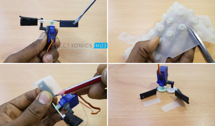
Step 13
- The surface of the plastic is very smooth and might not be able to get a good grip of the object.
- For this, take a rubber or silicon material and cut it into the size of the holder part. This rubber will add some grip to the robot arm.
- Make two such rubber part for both the parts of the holder arm.
Step 14
- Now, we need to glue this rubber to the plastic bit. Since glue won’t be able to fix the rubber to the plastic, we used double sided tape.
- Attach the rubber part to one side of the tape and attach the other side of the tape to the plastic piece of the arm.
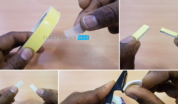
Step 15
- Finish both the ends of the arm with rubber grip and double sided tape.
- Test and see the grip of the arm. It would be better than plain plastic holding the object.
- This step completes the construction related to the holder servo and the actual holder arm. From the next step onwards, we will proceed with the construction of the first vertical servo.
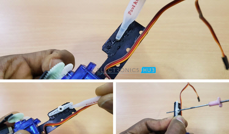
Step 16
- Take another piece of plastic (roughly about 7 – 9 CM) and glue it to the side of the holder servo, just below the compound.
- This piece of plastic will connect the holder servo and first vertical servo.
- Now, glue the wires of the holder servo at the bottom of the holder servo and also to the side of the plastic so that it won’t be in the way of robotic arm’s movement.
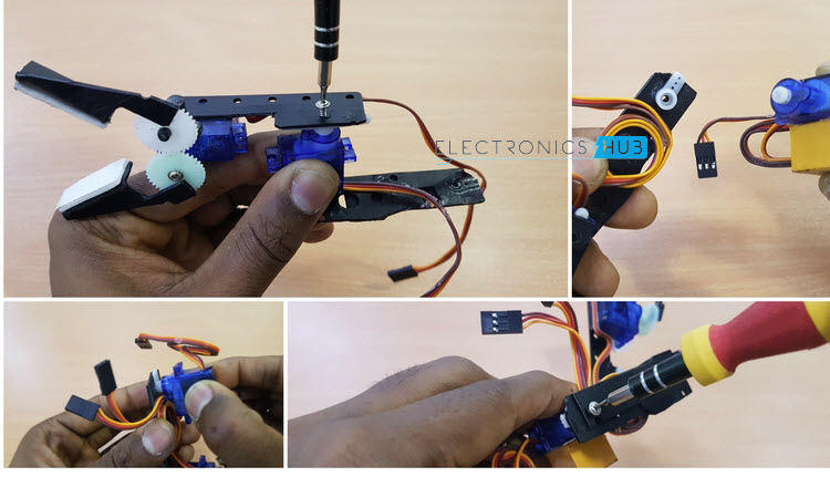
Step 17
- In order to fix the first vertical servo to the plastic, we will first glue a servo horn to the plastic as shown.
- Now, drill a hole through the center of the servo horn, so that the first vertical servo can be properly screwed.
Step 18
- Take another piece of plastic as shown in the image and slightly heat at one end and bend it 90 degrees.
- The bent part must be glued to the first vertical servo.
Step 19
- At this point, we can fix the first vertical servo to the plastic of the holder servo and screw it properly.
Step 20
- We will fix the servos later. Now we will manage the wire of the first vertical servo by gluing it to the plastic it is attached to.
- Next, we will take a small servo horn and glue it at the end of the plastic. This horn will be connected to the second vertical servo.
- Also, drill a hole through the servo horn and plastic for the servo to be screwed.
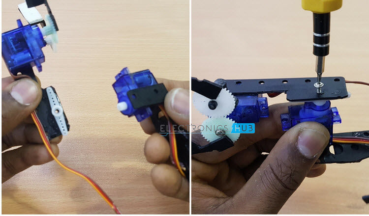
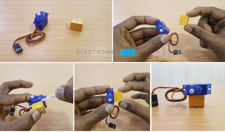
Step 21
- Take the second vertical servo and a small cuboid like structure for additional support.
- Glue the second vertical servo to the cuboid structure. This cuboid structure will give some additional height to the servo.
Step 22
- In case the holder servo and first vertical servo are not fixed earlier, fix them now.
- Also, attach the second vertical servo to the arm at the small servo horn with the help of a screw.
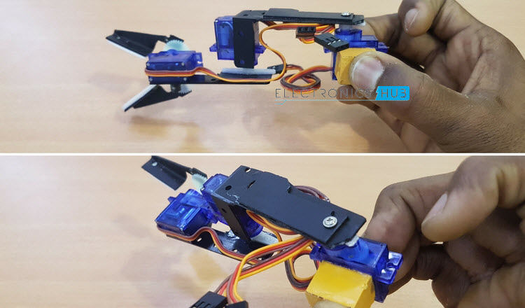
Step 23
- The final structure will be something as shown in the following images.
Step 24
- Now, glue the cuboid structure to the zero board, near the servo connectors we fixed.
- Also, connect the servo wires to their respective connectors on the board.
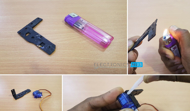
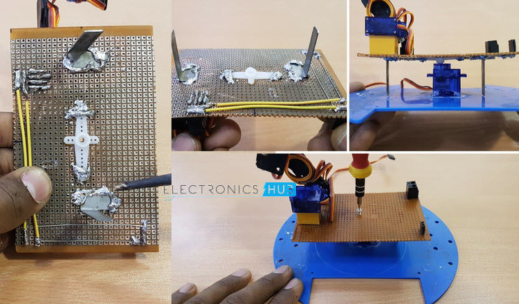
Step 25
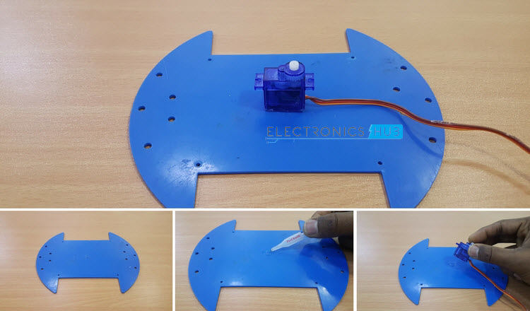
- Now, we will connect the final servo, which is the horizontal servo. This servo will help in the horizontal i.e. left – right movement of the robot.
- For this, take any smooth, solid surface as shown in the image.
- Glue the horizontal servo at the center of the board. Make sure that the servo is glued firmly.
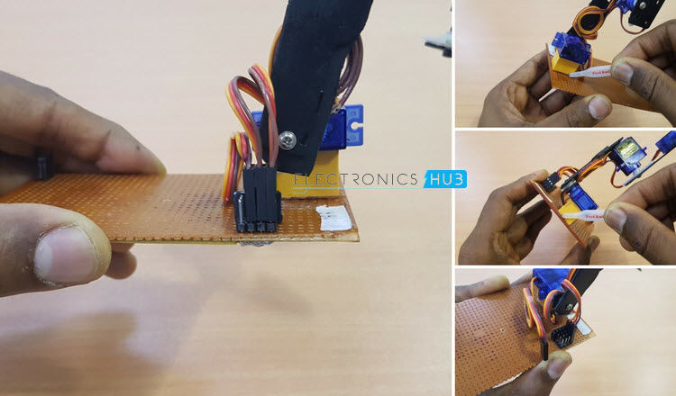
Step 26
- If you remember, in steps 3 and 4, we fixed a servo horn at the bottom of the board.
- Now, we need to fix the horizontal servo to this servo horn with the help of a screw.
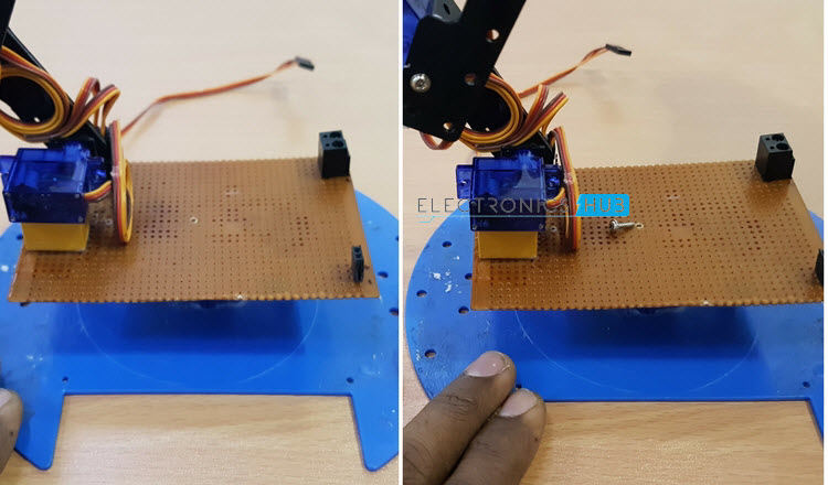
Step 27
- But before screwing the servo, if you notice, the structure above the horizontal servo is not stable and it wobbles easily even when slightly touched.
Step 28
- So, we need balance the structure with the help of two supporting objects.
- We took two soft metal parts from an old transformer. They are strong enough to support structure and soft enough to cut easily.
- Cut those parts and bend them in a desired shape as shown in the image.
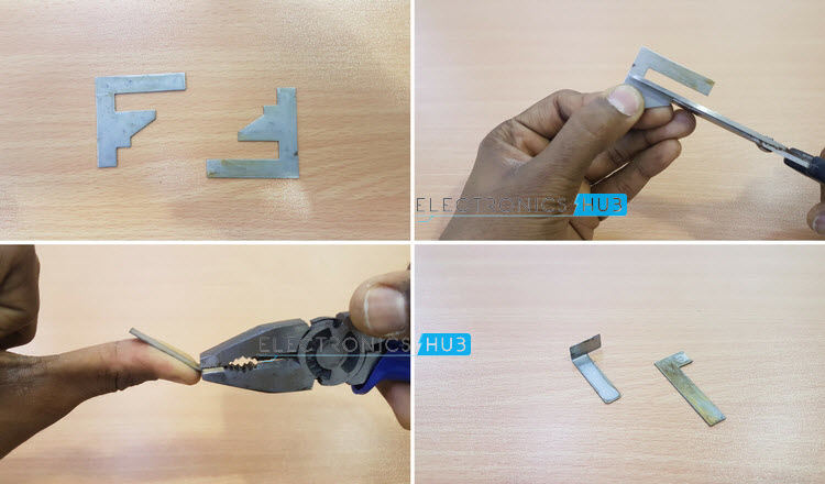
Step 29
- Glue the supporting structure to the board. If the glue doesn’t hold the metal piece, solder some lead over the metal part.
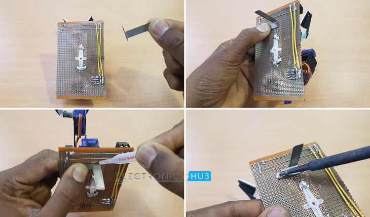
Step 30
- Finish off both the supporting pieces and glue them properly.
- Now, fix the horizontal servo to the servo horn on the zero board. Check and see if the structure wobbles. If it does, adjust the height of the supporting pieces.
- Now, you can screw the horizontal servo firmly to the board. With this step, we have completed the maximum construction of the robotic arm.
Step 31
- In this step, we will fix the Arduino UNO board to the zero board. For this, take some double sided tape and fix it on the top of the zero board, as shown.
- Fix the Arduino on the board with the help of this tape.
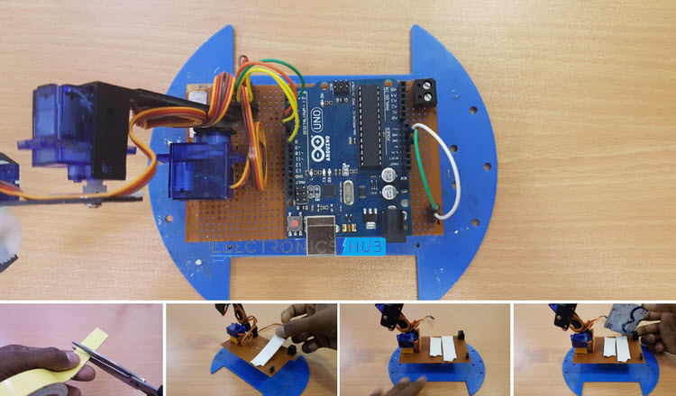
Step 32
- Make necessary wiring connections to the Arduino and also connect the power supply wires between the board and Arduino.
- With this step, we have successfully completed the construction of the Robotic Arm.
Step 33
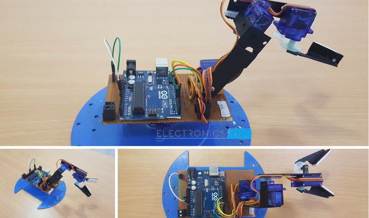
- The final look of the completed Robotic Arm will be something like this.
- This step – by – step explanation of the construction is just to demonstrate the procedure of the construction. We have constructed the Arm with the parts that are readily available with us and didn’t find it that difficult with the design. You do not have to follow the exact same steps, if you are planning to build a Robotic Arm.
CODE for Manual Operation
Now you completely know how to build Arduino robotic arm that has major applications in detecting and dismantling of bombs and in large-scale industries to speed up the process.
For those who have a keen interest in crafting Arduino robot projects, We provided Best Arduino Robot Kits. Read the complete article and pick the best one that matches your requirements.
Recommended reading:

43 Responses
thank’s for the nice work
although, where’s the arduino code
code for autonomous
Brilliant work.
Though is it possible that you provide us with the arduino code, please.
We will update the code asap.
does this mean it can be only manually operated
good work, but the main thing is where is the arduino code??
Can you please provide the code for this robotic arm?
Hi Anusha!
May I know how does the robotic arm know the position of the cube (I assumed based on the shape) it should pick? Do you include any sensor?
Hi, The position of the cube is pre-programmed using step-by-step alterations of the servo motors. This is done to fix three positions of the cubes in the Arduino. We did not use any sensors or object detection. Just the good old manual calibration.
please upload code immediately
Please give us a code.
Nice setup please how can I get the codes
can u plz,,,provide the code asap at “kssoni716@gmail.com”
Good project and better work, but ….. without the code, nothing can be done, you say that, soon, will update the code, I ask you, when the project started did not have the code ?.
We can not prove, in any facet of knowledge, whether, the others can not replicate the essay. Nothing is, nothing is left.
Code
Dear sir, great project of yours, and also works correctly …… Great !!!!
It would be possible for you to put the code on this page. I check that I am not the only one that requests it, or … maybe you need to pay a certain amount of money for the code? If so, do not hesitate to contact me, to my email address, indicating The economic conditions. Thank you.
I await your response, carefully.
Daniel.
Check out the updated project. Arduino & Bluetooth Controlled Robotic Arm for more info.
I wanted to know how much weight can the arm lift. Will it be able to lift small metal pieces?
Hi,
This Robotic Arm isn’t for heavy lifting (as it is mostly made from plastic scrap).
provide the code please
Please give me the code ………….
Code
can somone please provide the code ?
very helpful…please send us the code…thank you
how much is the total cost of this model ?
can you please quote for me .
Thankyou
There will be an upgraded model of this with 3D Printed Parts, Metal Gear Servos, Bluetooth control and a dedicated Android App. We will update is soon.
Can you still use a normal breadboard instead of the zero PCB?
good
hi there do you have a daily or week email that one can sign up for.
hey could you possibly make a list of required materials, it will make my life much easier
thx
Hi,
Aswome work,
Instead of fixed position, Is it possible using X,Y Coordinates to perform the action?
Awesome work.
Though is it possible that you provide us with the arduino code, please.Make Such more projects
Its help lots.
code pls..
nice project
very good project,
can you please upload a video about the explanation of the code that you have provided.,
thank you.
osm project
brother i am not understant the arduino codes.
Hi ravi!
Wonderful project of yours………only there’s request that please provide the arduino code for its automatic operation……
Waiting for your response….
Thankyou
Anurag
Can I get the list of the parts required?
Sir without using pcb board how can we do all connection on breadboard can you please share that information with circuit diagram
Please mention the code but an amazing work
Could you please show a wiring diagram?
Can you please add comments alongside the lines of code to explain what that particular does? It would be helpful to people just stepping into robotics.
will it work for color sorting if i use particular sensor for it