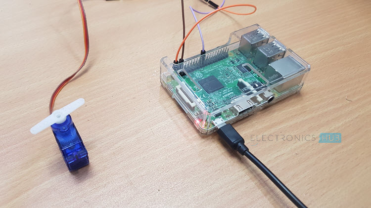
In this project, we will learn about Servo Motors, Raspberry Pi Servo Motor Interface and How to Control a Servo Motor using Raspberry Pi and Python. For this project, we will be using the Raspberry Pi 3 and Tower Pro SG90 Servo Motor.
Overview
Interfacing a Servo Motor with Raspberry Pi is an interesting topic as Servo Motors are the main components of a Robot and with the help of Raspberry Pi, you can have endless opportunities in Robotics.
A Servo Motor is a simple device that consists of a DC Motor, Gears and a Feed Back based Position Control System. The main advantage of a Servo Motor is its ability to hold the angular position of its shaft.
There are several varieties of Servo Motors you can choose from. Two of the most common Servo Motors are Tower Pro SG90 and Tower Pro MG90S.
SG90 is a plastic gear motor whereas MG90S is a metal gear motor. In this project, I’ll be using the SG90 Servo Motor.
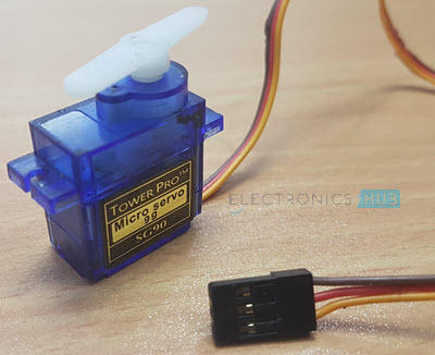
The Tower Pro SG90 Servo Motor Consists of three Pins: PWM (Orange or Yellow), VCC (Red) and GND (Brown). The VCC and GND pins must be connected to +5V and GND of the power supply.
PWM or Signal Pin of the Servo Motor must be connected to the PWM Output of the Controller (Raspberry Pi). Based on the width of the Pulses from the PWM signal, the angle of the Servo Motor’s shaft will vary.
How to Control a Servo Motor?
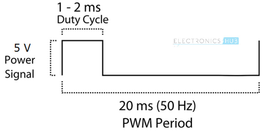
In order to control a Servo Motor, you need to use a technique called Pulse Width Modulation or PWM. In PWM technique, you will be sending a pulse of variable width and the position of the Servo Motor’s shaft will be set by the width or length of the Pulse.
The frequency of the PWM Signal is a fixed value and is dependent on the type of the Servo Motor. In our case, both SG90 and MG90S Servo Motors have a PWM Frequency of 50Hz.
At 50Hz i.e. a period of 20ms, the minimum pulse width is 1ms and the maximum pulse width is 2ms. Most servo motors can have a sweep area of 180 degrees i.e. 90 degrees on either side of the neutral position.
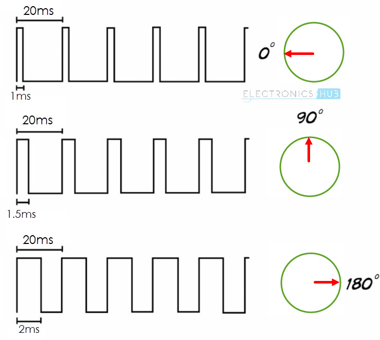
When the pulse width of the PWM Signal is 1ms, the position of the servo is all the way to the LEFT. The Duty Cycle of this position is (1ms/20ms) x 100 = 5%.
Similarly, for pulse widths of 1.5ms and 2ms, the position of the servo is MIDDLE (with duty cycle of 7.5%) and far RIGHT (with duty cycle of 10%).
Raspberry Pi Servo Motor (SG90) Interface
Interfacing a Servo Motor with Raspberry Pi will help you in implementing complex projects like Web Controlled Servo, RC Robot, IoT Servo Control etc.
Also, the first thing you need to learn while working on Robotics is how to control a Servo Motor.
So, in this project, I’ve implemented a simple control of Servo Motor with the help of Raspberry Pi. Now, Raspberry Pi has only one pin that is capable of producing PWM Pulse. It is Physical Pin 12 i.e. GPIO18.
But I have connected the PWM pin of Servo to GPIO25 (Physical Pin 22) of Raspberry Pi, in order to check whether the project will work or not. It worked without any hassle.
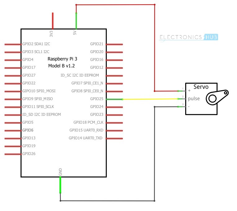
Circuit Diagram of Raspberry Pi Servo Motor Interface
The following Fritzing image shows the circuit diagram of the Raspberry Pi Servo Motor Interface.
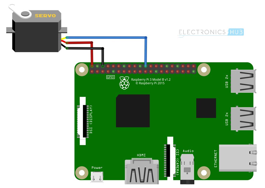
To understand more clearly about the connections, the following wiring diagram might be helpful.
Components Required
- Raspberry Pi
- Tower Pro SG90 Servo Motor (any Servo Motor can be used)
- Connecting Wires
- Power Supply
- Computer
Circuit Design
Connect the VCC and GND of the Tower Pro SG90 Servo Motor to +5V and GND pins of the power supply. Then connect the PWM Pin of the Servo Motor to Physical Pin 22 of Raspberry Pi i.e. GPIO25.
Make the ground common between Raspberry Pi and the Power Supply of the Servo Motor.
NOTE: I’ve connected the Servo Motor directly to the +5V pin of the Raspberry Pi. I would not recommend you to do the same.
Code
The code for Controlling a Servo Motor with Raspberry Pi is written in Python. The Python Script for the project is given below.
Working
The aim of this project is to understand the Raspberry Pi Servo Motor Interface and how to control a simple Servo Motor using Raspberry Pi.
Now, coming to the working of the project, we are going to use the PWM feature of the Raspberry Pi. As mentioned earlies, based on the Duty Cycle of the PWM Signal from the Raspberry Pi, the position of the Servo Motor will vary.
Since, 5% Duty Cycle of the PWM signal corresponds to extreme left position and 10% Duty Cycle corresponds to extreme right position, we need to vary the Duty Cycle between 5 and 10% to get a sweeping effect from the Servo Motor.
If you observe in the code, the duty cycle gradually rises from 5 to 10% with an increment of 0.5% in every step. Once it reaches the 10% mark, the reverse action will begin.
Applications
Interfacing a Servo Motor with Raspberry Pi and controlling the angle of rotation of the Servo can be helpful in several applications like:
- RC Car
- RC Plane
- Robot
- Quadcopter

One Response
Not a big fan of this method. It ties the RPi up just dealing with the software. My approach is to buy a PWM/Servo Hat/Board from Adafruit or Pimoroni and use that. The board take care of all the PWM side. One sends a command to the board to position the servo/PWM. Ok it costs more but I feel that the extra cost is justified.