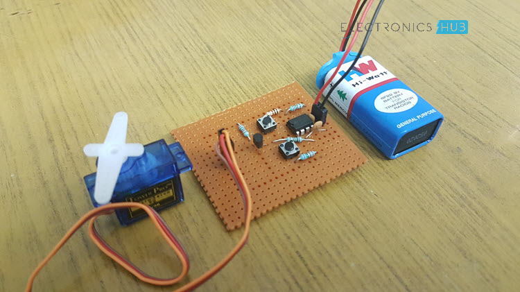
In this DIY project, I will show you how to make a Simple Servo Motor Tester Circuit and how to use circuit in order to check whether your servo motor is working properly or not.
Introduction
When it comes to hobby projects and beginner electronics projects, Servo Motors are one of the important devices that we often use. Servo Motors are the main work horses in a variety of projects like Solar Tracker, Robotic Arm, Obstacle Avoiding Robot and many other small as well as complex projects.
When using Servo motors in your projects, you might have faced issues like the servo motor not working properly or doesn’t provide complete (possible) rotation. In situations like these, a simple Servo Motor Tester Circuit will be helpful.
A Servo Motor Tester is a simple circuit designed specifically for testing the functionality of a Servo Motor. You can also use this circuit to test a newly bought Servo Motor to check if it is a faulty one.
NOTE: Even though Servo Motors are a huge part several industrial and automations applications, I am limiting my discussion of this project to Servo Motors like TowerPro SG90 (Plastic Gears) and TowerPro MG90S (Metal Gears), which are often used in hobby and DIY projects.
How to make a Simple Servo Motor Tester Circuit?
In order to design a simple Servo Motor Tester Circuit, you need to first understand how a servo motor works. I won’t go into minute details of how a servo motor works but give a general idea.
Basically, a Servo Motor works on the principle of pulse width modulation or PWM. The angle of rotation of the servo motor is controlled by the PWM Signal applied to the Pulse Pin (or Control Pin) of the servo motor (usually, the Orange wire).
To be more specific, the duration of the pulse provided to the Control Pin will decide the angle of rotation of the servo. We know that most of the servo motors available today can be rotated from 0 degrees to 180 degrees. When the duration of the pulse is 1 milli second (1 ms), the shaft of the servo is rotated to 0 degrees.
If the duration is increased to 1.5 milli seconds (1.5 ms), the servo rotates to 90 degrees. This is the default position. When the duration of the pulse is further increased to 2 milli seconds (2 ms), the servo rotates all the way to 180 degrees.
So, in order to make and design a Servo Motor Tester circuit, you need to generate a PWM Signal and also control the duration of the pulse. In order to generate the PWM or Pulse Width Modulated Signal, I have used the good old reliable 555 Timer IC.
Circuit Diagram of Servo Motor Tester
Components Required
- 555 Timer IC
- Servo Motor under Test (like SG90 or MG90S from TowerPro)
- Push Buttons X 2
- 10KΩ Resistors X 2
- 10Ω Resistors X 2
- 750KΩ Resistor (* for info in circuit design)
- 100nF Capacitors X 2
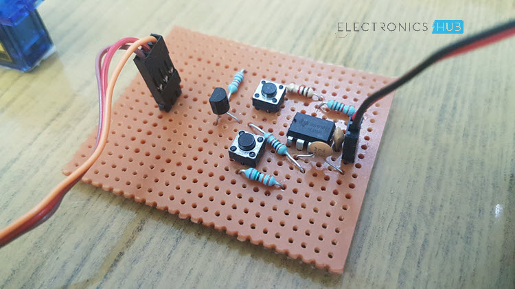
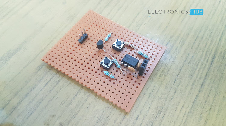
- Perf Board or Breadboard
How to Design Servo Motor Tester Circuit?
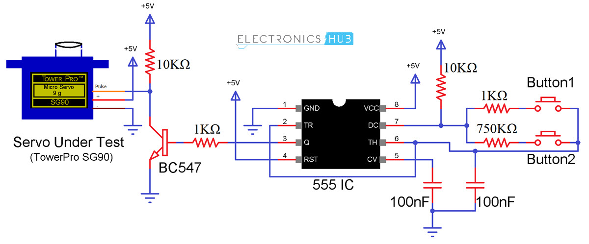
First, connect the Pins 8 and 4 (VCC and RST) of the 555 Timer IC to +5V supply and connect the Pin 1 (GND) to ground. Short Pins 2 and 6 (TR and TH) and connect a 100nF Capacitor between Pin 6 and GND and another 100nF Capacitor between Pin 5 (CV) and GND.
Now, connect a 10KΩ Resistor between Pin 7 (DIS) and +5V. Now comes the tricky part. Connect two Resistors of 1KΩ and 750KΩ between Pin 7 and 6 through individual Push Buttons as shown in the circuit diagram.
The choice of 750KΩ Resistor is not mandatory. Theoretically, a 12K resistor will produce the necessary 2ms pulse but practically, I did not get that value. So, with a lot of trial and error setup, I got satisfactory results with 750KΩ. Your circuit may not be the same. So, I suggest starting with 12K and gradually increasing with all the other value same until you get the result.
Now, the output of the 555 Timer IC i.e. the Pin 3 (OUT) is connected to an NPN Transistor (BC547) through a current limiting 1KΩ Resistor. The emitter terminal is connected to GND and the Collector terminal is connected to the Pulse pin of the servo motor as well as a 10KΩ Pull-up resistor.
Working
The working of this Simple Servo Motor Tester Circuit can be easily understood if you are familiar with the working of 555 Timer IC in Astable Multivibrator operation. 555 Timer IC is configured to operate in Astable Mode i.e. Square Wave mode.
In this mode, the width of the pulse can be modified by varying the values of resistor R2 i.e. the resistor between Pin 7 and 6. So, I have used to resistors with two push buttons. When the first button is pressed, 1KΩ Resistor is connected and the pulse duration is 1ms. This makes the servo to rotate to 0 degree.
When I press the second button, the other resistor (in my case 750KΩ) is connected and will generate a 2ms pulse duration. Hence, the servo will rotate to 180 degrees.
Conclusion
A simple but efficient Servo Motor Tester Circuit is designed in this project, which can be used to test the working small servo motors like TowerPro SG90 or TowerPro MG90S.

One Response
Excellent