In this ESP8266 WiFi Module Project, we will learn about WiFi Controlled LED using ESP8266 and Arduino. I will show you how to control an LED connected to the Digital I/O Pin of the Arduino over WiFi Network using the ESP8266 WiFi Module.
Overview
The ESP8266 WiFi Module is an interesting addition to the makers and hobbyists’ community as it allows us to integrate WiFi and Internet into our DIY Projects.
IoT or Internet of Things is one such area which can be implemented using a variety of sensors connected to a Microcontroller like Arduino and ESP8266 WiFi Module to access the sensor data from anywhere in the World.
Before thinking about big IoT projects, let us begin exploring the ESP8266 WiFi Module and implement a small but useful project called WiFi Controlled LED using ESP8266 and Arduino.
I have already introduced to you about the ESP8266 WiFi Module in my GETTING STARTED WITH ESP8266 AND ARDUINO Project. Refer to that project first in order to learn about the basic information on ESP8266 WiFi Module, its Pin Diagram, pin configuration and how to interface ESP8266 with Arduino.
IMPORTANT NOTE:
- In my second project on ESP8266 WiFi Module, I have shown you How to flash the AT Command Firmware onto the ROM of ESP8266 WiFi Module.
- It is very important that you first implement that project i.e. make sure that your ESP8266 WiFi Module has AT firmware installed on it.
- If you have programmed your ESP8266 WiFi Module with other program (like Blink, for example), then you must flash the firmware. If your ESP module is already has the AT Commands firmware, then leave it as it is.
Concept behind WiFi Controlled LED using ESP8266 and Arduino
Before getting into the details of the project like the circuit diagram, components, connections and the code, let me take you through the concept behind the WiFi Controlled LED using ESP8266 and Arduino.
The idea behind the project is very simple. Connect an LED to the Arduino Board. This LED must be connected over WiFi i.e. within a local network through a Smart Phone or a Laptop.
For this, use the ESP8266 WiFi Module and interface it to Arduino through Serial Communication. Arduino will command the ESP8266 module to get connected to a WiFi network and receive data from the client (an HTML page).
Based on the information sent by the client (with the help of a Web Browser), the Arduino will either turn ON or OFF the LED. That’s it.
Circuit Diagram
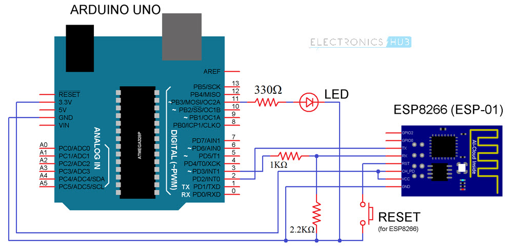
The circuit diagram for the WiFi Controlled LED using ESP8266 and Arduino project is shown I in the image below.
Components Required
- Arduino UNO [Buy Here]
- ESP8266 WiFi Module
- LED
- 330Ω Resistor (1/4 Watt)
- 1 KΩ Resistor (1/4 Watt)
- 2.2 KΩ Resistor (1/4 Watt)
- Push Button
- Connecting Wires
- Mini Breadboard
Circuit Design
I have used the software serial feature of the Arduino and made its digital pins 2 and 3 as RX and TX. These pins must be connected to TX and RX Pins of the ESP8266 WiFi Module.
NOTE: I have used a level convertor consisting of a 1 KΩ Resistor and a 2.2 KΩ Resistor before connecting the TX Pin of Arduino (Pin 3) to the RX Pin of the ESP8266.
An LED is connected to the Digital I/O Pin 11 of the Arduino. (This is the LED that we will be controlling over WiFi).
Coming to the rest of the connections with respect to the ESP8266, it’s VCC and CH_PD pins are connected to 3.3V of the Arduino and GND is connected to, well the GND pin of the Arduino. A Push Button is connected between RESET of ESP8266 and GND.
Both the GPIO Pins of the ESP8266 i.e. GPIO0 and GPIO2 are left open as we won’t be using those pins in this project.
Code
The following is the code that is to be uploaded into Arduino. It will configure the WiFi in the ESP8266 Module as well as check for the data from the HTML page (will be discussed later).
HTML Code for Sending Data to ESP8266
In order to create an interface for the project, I have created a simple HTML based webpage. The HTML code for this webpage is given below.
Download this HTML Code (save it as .html file).
This HTML webpage uses the JavaScript library “jQuery.js”. Download this library from here and place it in the same folder as the .html file.
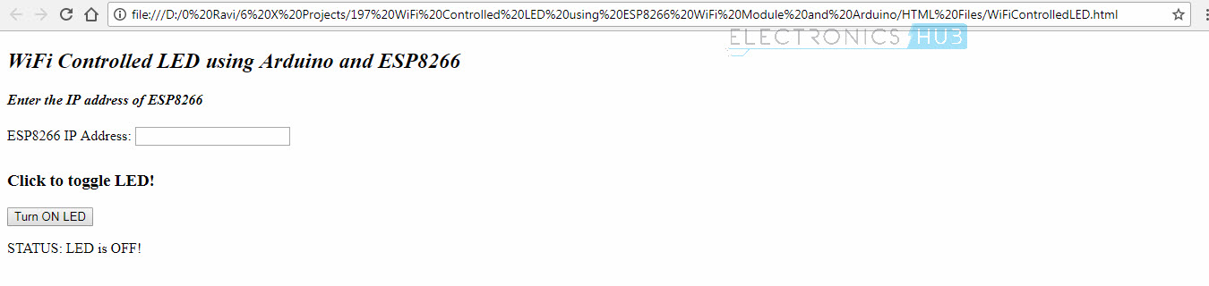
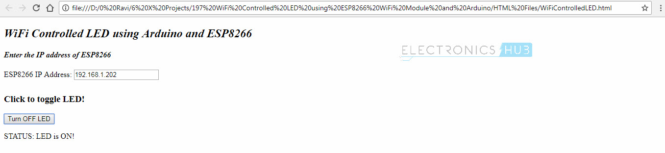
So, your webpage folder consists of two file: one “webpage.html” file and a “jQuery.js” file. Open the HTML file using any web browser. The interface looks like this.
Working of WiFi Controlled LED using ESP8266 and Arduino Project
Upload the Arduino Code provided above to your Arduino Board after making all the necessary connections. Once the code is uploaded, open the Serial Monitor of Arduino. You can see the progress of the setup done on the ESP8266 WiFi Module.
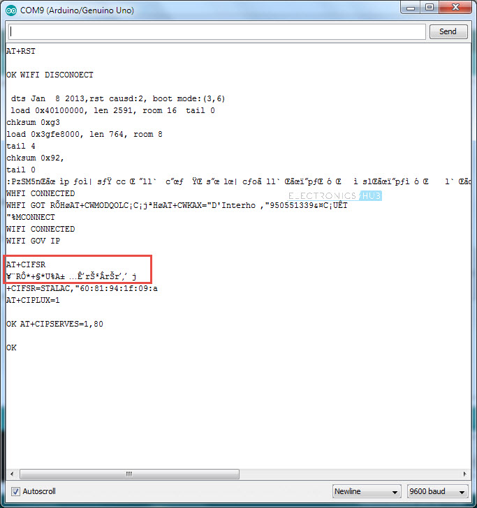
Some of the information in the above image looks garbage but I assure that correct data is transmitted. If you got a clean response, you can find the IP Address of the ESP8266 Module at the highlighted place in the image above.
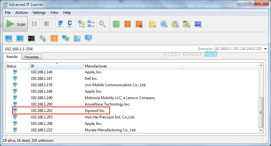
Since I couldn’t find the IP Address from Serial Monitor, I had to look up for it using another tool called “Advanced IP Scanner”.
Now, open the webpage that you saved earlier and enter this IP Address in the IP Address field provided. After entering the IP Address, you can click on the Button on the page to turn ON and OFF the LED.
Conclusion
A simple project called WiFi Controlled LED using ESP8266 and Arduino is designed here where an LED connected to Arduino is controlled over WiFi (within the same network).
Any device connected in same WiFi Network can control the LED with the help of a simple HTML webpage.
The next step or an advanced version of this project will be controlling the LED over internet i.e. from anywhere in the World (involves PORT Forwarding).

20 Responses
Nice
Thank you very much!
Would you recommend any tutorial for port forwarding?
I wouldn’t recommend port forwarding. But there is a site called portforward.com
Check it out.
Good Tutorial but you did not tell me why there is a reset ? how to use that wire?
when to press the push button? I am getting disconnected in output it does not connect. Have checked with ip scanner but fails…however if i reset arduino and run at commands directly then it connects…
Sir I am using arduino version 1.8.3 , but iam not able to find esp 8266 in the boards manager please help me to solve the problem.
You need to add a script in Arduino IDE to get ESP in boards list. More information can be found here: https://www.electronicshub.org/esp8266-arduino-interface/
Great stuff. I’m new with this. I’ve got it working, but there is a lot of garbage in the serial text so the led doesn’t work with every click of the button..
Anyway idea how to get rid of the Garbage?
Even I got some garbage values (as you can see in the post). Tried a few different things but couldn’t get rid of the garbage. Any suggestions from experts?
change the baud rate in serial moniter…..if it still can’t work then reset the nodemcu by reset button…if then it cant work then u sure that your node mcu or any microprocessor cant work prperly…so change that microcontoller..
It gets hang after pressing the same button for 4-5 times!!!!
Hello sir In this project “WiFi Controlled LED using ESP8266 and Arduino ” board selection will be arduino uno or generic esp8266 if you tell it will be very helpfull thank you… waiting for reply…….
Arduino UNO
How to connect to wifi network in this project?
sir can we return a response from arduino to the http request from web server ?
Hi, thank you for the tutorial, I would like to know why you changed the RX/TX pin from GPO0&1 to GPO 2&3. Is it possible to leave it without changing?
Can you add more LEDS to the arduino board to be controlled also and how please?
We uplaoded the code as per ur instructions bt still in serial monitor nothing output is shown.Serial monitor is just seen blank.
when in browser we call (https://192.168.1.***/?led=ON) i want esp8266 respond and display message that is OK or no on that page, can we do that with AT Commands? or any other way…
Sir how to add jquery library when i click on the download button it doesnt work ?
At Tools>Board, which board are you using? What should I configure for the board I’m using?