Introduction
In this project, I will show you how to design a Variable Voltage Power Supply from Fixed Voltage Regulator like 7805 IC.
78XX and 79XX are the two series of three pin voltage regulator available in the market. 78XX series of the voltage regulator is for the positive voltage supply i.e. if you need a +5V supply, then 7805 voltage regulator can be used. While 79XX series is for negative supply, i.e. if you need a -5V supply, then 7905 regulator is used.
Voltage regulators like 7805 are used to offer fixed voltage at the output terminal and does not depend on the variations at input voltage supplied (as long as it is greater than the required voltage).
What if you want a range of output voltage with the help of a single Linear Voltage Regulator IC? It is possible to implement this idea. I will now show you how to implement a Variable Voltage Power Supply from Fixed Voltage Regulator.
LM317 is a simple Variable Voltage Regulator IC that can be used to produce voltages in the range of 1.5V to 37V. But you can produce the same from a fixed voltage regulator like 7805 as well (although not the same range). This can be achieved by adding two resistors. Let us see how it is implemented here.
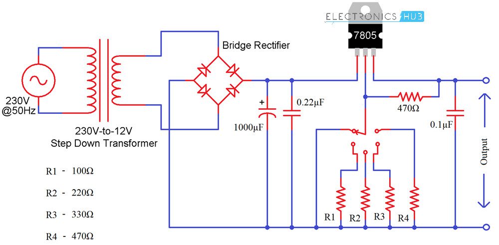
Circuit Diagram of Variable Voltage Power Supply From Fixed Voltage Regulator
Components Required
- 230V to 12V Step Down Transformer
- Bridge Rectifier
- 7805 Regulator IC
- 1000μF Capacitor
- 0.22μF Capacitor
- 0.1μF Capacitor
- 470Ω Resistor x 2
- 100Ω Resistor
- 220Ω Resistor
- 330Ω Resistor
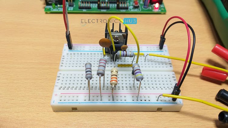
- Mini Breadboard
- Connecting Wires
Circuit Design
Initially, the primary of the 230V to 12V Step Down Transformer is connected to the AC Mains supply while the secondary is connected to a bridge rectifier. The output of the bridge rectifier is filtered out using a capacitor and is given to the 7805 Voltage Regulator IC.
A 0.22μF Capacitor is connected between INPUT and COMM (GND of 7805) while a 0.1μF Capacitor is connected between OUTPUT and COMM.
Now coming to the interesting part. A 470Ω Resistor is connected between the COM and OUT. A rotary switch is used to switch between output resistors and the following resistors are connected to the switch: 100Ω, 220Ω, 330Ω and 470Ω.
WARNING: If you are using AC Mains Supply as the source, be extremely careful when making the connections.
Principle
A simple project where a Variable Voltage Power Supply from Fixed Voltage Regulator is implemented here. The main principle behind the working of this project is very simple.
Connect two resistors R1 and R2 as shown in the image below: one between the output and GND Pin and the other between GND Pin and GND of power supply.
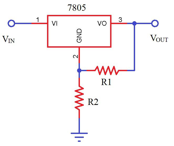
The amount of current flowing through R2 is a combination of current through R1 and the standby current of 7805. Depending on the output voltage requirement, we can calculate the value of this resistor and finally the output voltage can be calculated as follows.
VOUT = VREG + R2 * (VREG/R1 + IS)
where VREG = 5V (for 7805) and
IS = standby current of 7805 (≈2.5mA).
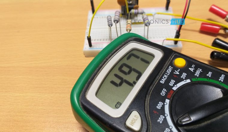
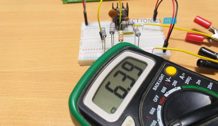
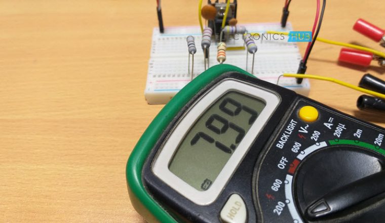
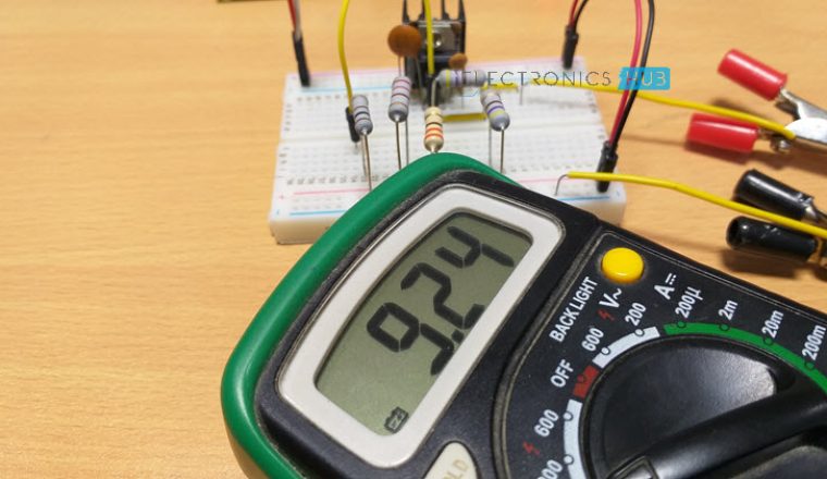
Based on the above calculations, you can get anywhere between 5V and 12V using a 7805 Regulator from a 12V Supply.
The following images show the range of outputs obtained with a 7805 Voltage Regulator IC.
How to Calculate the Value of Resistance for the Different Voltages?
Imagine that the resistor which is attached between the com terminal and the output terminal of regulator has a value of 470Ω. This implies that the value of current is 10.6 mA (as V =5V furthermore V=IR).
Among the rotary switch and ground there is some amount of standby current of 2.5 mA approx. Hence about 13.1 mA of overall current is available.
Now assume that from the circuit we need 5V to 12V. With the regulator output we directly got 5V minimum. While if there is a need of 12V, then between com and output 5V is available and for the rest 7V we need to select the appropriate value of the resistor.
Here R =?
V = 7V
I =13.1mA
Therefore V =I*R
R = 543ohm
Hence, we have to attach resistor of 543 Ω with 470 Ω so to obtain the wanted output i.e. 12V. While it is difficult for us to get such a value of the resistor in the market so we can use the nearby value of the resistor i.e. 560 Ω.
Now if we wish to have some other voltage from 5V to 12V then we have to attach some other value of the resistor.
Suppose we need 6V, then
V =6V
I = 10.6mA
R = 6V/10.6mA
R = 566 Ω
But the resistor R1 is already on 470Ω which is already connected in the circuit, hence for 6V value of the resistor will be 100 Ω approximately (566-470=96).
In the same manner for different voltages different value of resistance will calculated. In spite of the different values of resistors available, a variable resistor can be used in the circuit to get different values of voltage.
Important Notes
- When switching from one resistor to other, the load will get 12V.
- So, before switching, make sure that the load is disconnected (or you can completely switch off the power supply, make a switch and then switch on the power supply).
Related Post: Mains Operated LED Light Circuit

6 Responses
I am a student of final year EEE. i am no select our project.
Hi!
Once check the following links:
https://www.electronicshub.org/electronics-projects-ideas/
https://www.electronicshub.org/eee-projects-ideas/
I am a Final year student of Electrical & Electronics Engineering. Please help me Our project selection of the final course.
Once find the following link: https://www.electronicshub.org/embedded-systems-projects-ideas/.
Pardon for this comment, isn’t it dangerous during switch transsion….with pin 2 at float, output voltage will be equal to input voltage and may damage the load…
Vary interesting article. I am a TV mechanic in 1980 to 1990. And also runs an institution for TV mechanics.