In this DIY Project, I will show you how to build a simple Lead Acid Battery Charger Circuit using easily available components. This circuit can be used to charge Rechargeable 12V Lead Acid Batteries with a rating in the range of 1Ah to 7Ah.
Introduction
Lead Acid Batteries are one of the oldest rechargeable batteries available today. Due to their low cost (for the capacity) compared to newer battery technologies and the ability to provide high surge currents (an important factor in automobiles), Lead Acid Batteries are still the preferred choice of batteries in almost all vehicles.
The main concern with any battery is it discharges over time and must be recharged so that it can provide the necessary voltage and current.
Different batteries have different strategies of charging and in this project, I will show you how to recharge a lead acid battery using a simple Lead Acid Battery Charger Circuit.
Warning: Before proceeding further, I want you to know that this circuit is tested in a specific test conditions and we do not guarantee that it will be 100% successful. Try this circuit at your own risk. Take all the necessary precautions as you might be handling Mains Voltage and high potential DC.
How to Recharge a Lead Acid Battery?
To charge a battery from AC we need a step down transformer, a rectifier, filtering circuit, regulator to maintain the constant voltage. Then we can give the regulated voltage to the battery to charge it. Think if you have only DC voltage and charge the lead acid battery, we can do it by giving that DC voltage to a DC-DC voltage regulator and some extra circuitry before giving to the lead acid battery. Car battery is also a lead acid battery.
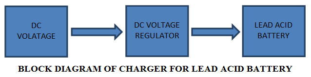
As seen in the above block diagram, a DC voltage is given to the DC voltage regulator. The voltage regulator used here is 7815, which is a 15V regulator. The regulated DC out voltage is given to battery. There is also a trickle charge mode circuitry which will help to reduce the current when the battery is fully charged.
Related Post – 12v Portable Battery Charger Circuit using LM317
Circuit Diagram
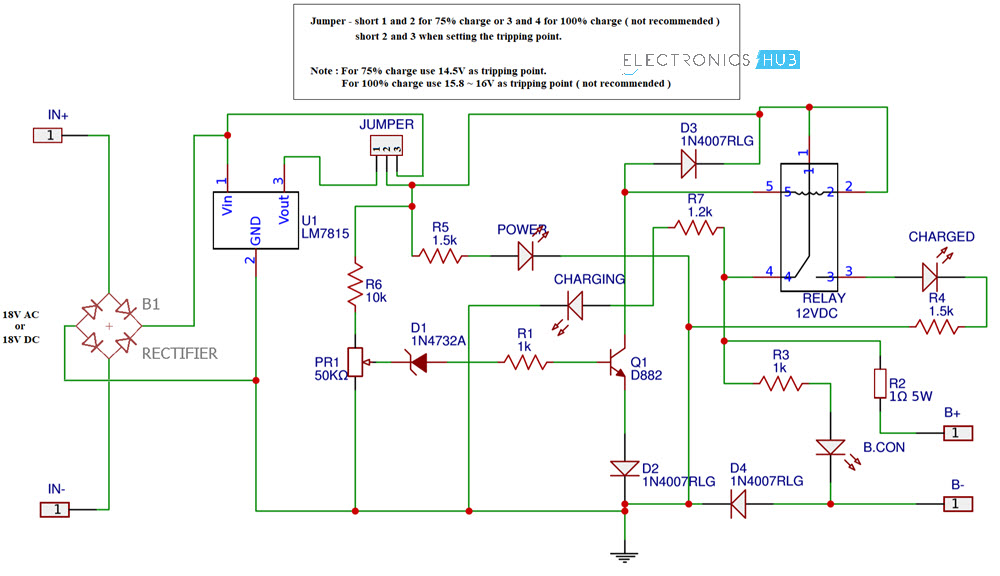
The circuit diagram of the Lead Acid Battery Charger is given below.
Components of Lead Acid Battery Charger Circuit
- 7815
- Bridge Rectifier
- Resistors – 1Ω (5W), 1KΩ x 2, 1.2KΩ, 1.5KΩ x 2, 10KΩ
- Diodes – 1N4007, x 3, 1N4732A (Zener)
- 2SD882 NPN Transistor
- LEDs x 4
- 50KΩ Potentiometer
- 12V Relay
Component Description
7815
The 7815 is a part of the 78XX series of linear voltage regulators. You might have used 7805 and 7812 which produce a regulated voltage of 5V and 12V respectively. Similarly, the 7815 Voltage regulator produces a constant regulated voltage of 15V.
Lead Acid Battery
Lead Acid Battery is a rechargeable battery developed in 1859 by Gaston Plante. The main advantages of Lead battery is it will dissipate very little energy (if energy dissipation is less it can work for long time with high efficiency), it can deliver high surge currents and available at a very low cost.
Calibrate the Circuit
Before seeing the working, let me show you how to calibrate the circuit. For calibrating the circuit, you need a variable DC Power Supply (a bench power supply). Set the voltage in your bench power supply to 14.5V and connect it to CB+ and CB- of the Circuit.
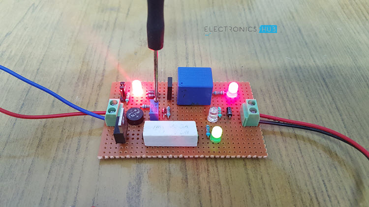
Initially, set the jumper between positions 2 and 3 for calibrating. Now slowly turn the 50KΩ Potentiometer until the “Charged” LED turns ON. Now disconnect the power supply and connect the jumper between 1 and 2. Your circuit is ready as all you need is a DC (or AC) supply of 18V.
NOTE
- The 14.5V we set in the calibration is called the Tripping Point. When the Tripping point is set to 14.5V, the battery will charge for about 75% of its capacity.
- If you want to charge 100%, then set the tripping point to ≈16V by removing the 7815 regulator and directly supplying 18V DC, but this is not recommended.
Circuit Explanation
- The circuit mainly consists of a Bridge rectifier (if you are using AC supply stepped down to 18V), 7815 Regulator, Zener Diode, 12V Relay and a few resistors and diodes.
- The DC voltage is connected to the Vin of the 7815 and starts charging the battery through the relay and the 1Ω (5W) resistor.
- When the charging voltage of the battery reaches the tripping point i.e. 14.5V, the Zener diode starts conducting and provides enough base voltage to transistor.
- As a result, the transistor is active and its output becomes HIGH. This high signal will activate the relay and the battery is disconnected from the supply.
NOTE:
- The battery should be charged with 1/10th it’s charging current.so the voltage regulator must generate 1/10th of the charging current produced by the battery
- Heat sink should be attached to the 7815 Regulator to the get the better efficiency.
Related Posts:

21 Responses
Thank you for your useful projects
please show the pcb diagram of this circuit
good
Please value of r6
This resistor is to protect the led.You can place a 2.2k resistor
Awesome ..?
how much dc volt input is to b given?
is this working.and is it charging fast
Please explain the calculation in the feedback section
what is the purpose of connecting capacitor (c3) and diode (d2) across the o/p?
The Ground of circuit is placed in wrong. It should be connected to Emitter of Q1. :))
What the purpose the potentiometer does?
one doubt here. in case power goes off during charging the battery, is int the current will flow back to circuit and LED will keep glowing? Do we need to put a diode to positive output to battery to stop the flow of reverse current ?
R1 are wrong connected. A NPN need (+) voltage between B-E to start working. In the application datasheet of LM317 it shows connected R1 to ADJ of LM317.
If you are talking about the circuit “Current-Limited 6-V Charger”, both circuits are same. You are right about using +ve voltage to starting NPN working, but working here means dropping the ref voltage to stop charging the battery. Normally, this transistor does not work, the ref voltage is determined by R3, R4 and R5 only.
same topology as datasheet sample “6V charger”
normally the transistor does not work, it works only when current too high
Great project. If you make a video demonstration much better. Thank you.
please i need the refference for battery charger using scr
Very descriptive post, I loved that bit. Will there be a part 2?.
Feel free to visit my upshot … best cord electric lawnmowers Agreenhand
Thank you for this information… It gives me more knowledge on the circuit connection
Very very good, thanks