Have you ever tried to design a variable regulated power supply? This article describes you how to design a variable power supply circuit . Till now we have seen a lot of power supply circuits, but the main advantage of this power supply circuit ifs that it can vary the output voltage and output current.
Do It Yourself – How Cellphone Battery Charger Circuit Works?
Variable Power Supply Circuits
Variable supply that can be varied from 1.2V to 30V at a current of 1 Amphere
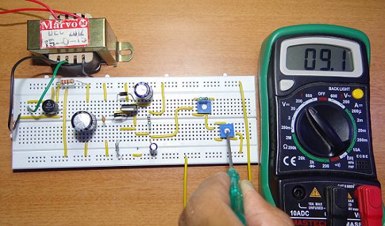
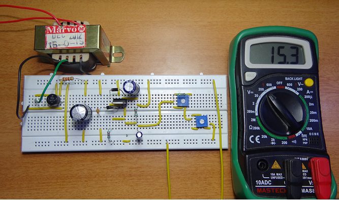
Output Video
Circuit Diagram
A Variable DC Power Supply is very important for electronics projects, prototyping and hobbyists. For smaller voltages, we normally use batteries as a reliable source.
Instead of using batteries, which have a limited lifetime, a variable DC power supply can be used which is implemented in this project.
It is a robust, reliable and easy to use variable DC power supply. The working of the circuit is as follows.
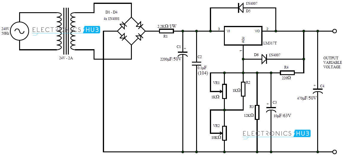
A transformer is used to step down the AC supply to 24V at 2A. A bridge rectifier is used to convert this voltage to DC.
This pulsating DC is filtered using the capacitor to get a clean DC and is given to LM317 which is a variable voltage regulator IC.
In order to vary the output voltage, two variable resistors of values 1KΩ and 10KΩ are used. 10KΩ POT is used for large change in voltage while 1KΩ POT is used for fine adjustments.
Depending on the settings of the POT, the ADJ pin of LM317 receives a small portion of the output voltage as feedback and the output voltage is varied.
A capacitor is used at the output of the voltage regulator so that the output voltage doesn’t have any spikes.
With the help of this variable DC power supply, the output voltage can be varied from 1.2V to 30V at a current of 1A. This circuit can be used as reliable DC source and acts as a replacement to batteries.
It is important to attach the voltage regulator IC LM317 to a heat sink as it tends to get hotter during operation.
Note
The above circuit uses only 15 v transformer at the input,so it can be varied maximum upto 15V. In order to increase the upto 30v input of 30v should be applied.
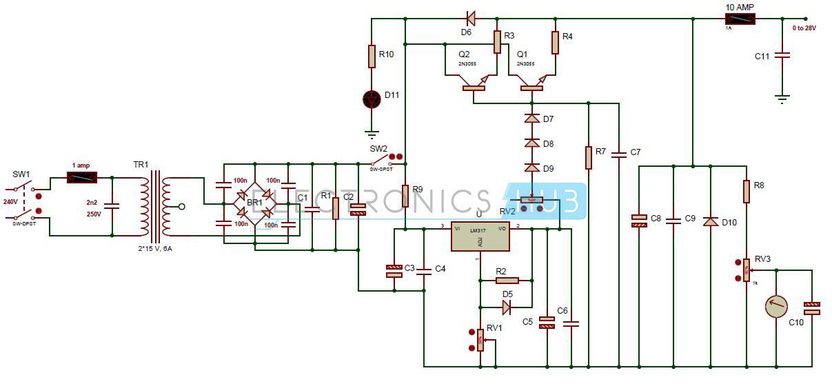
0-28V, 6-8A Power Supply Circuit Diagram using LM317 and 2N3055
This design can produce a current of 20 amps with little modification (use proper rating transformer and a huge heat sink with fan). Huge heat sink is required in this circuit, as 2N3055 transistors produce large amount of heat at full load.
Circuit Components
- 30V, 6A Step down Transformer
- Fuse F1 – 1 Amp
- Fuse F2 – 10 Amp
- Resistor R1 (2.5 watt) – 2.2k ohm
- Resistor R2 – 240 ohm
- Resistor R3, R4 (10 watt) – 0.1 ohm
- Resistor R7 –
- 6.8k ohm
- Resistor R8 – 10k ohm
- Resistor R9 (0.5 watt) – 47 ohm
- Resistor R10 – 8.2K
- Capacitors C1, C7, C9 – 47nF
- Electrolytic capacitor C2 – 4700uF/50v
- C3, C5 – 10uF/50v
- C4, C6 – 100nF
- C8 – 330uF/50v
- C10 – 1uF/16v
- Diode D5 – 1n4148 or 1n4448 or 1n4151
- D6 – 1N4001
- D10 – 1N5401
- D11 – LED red
- D7, D8, D9 – 1N4001
- LM317 adjustable voltage regulator
- Pot RV1 – 5k
- Pot RV2 – 47 ohm or 220 ohm, 1 watt
- Pot RV3 – 10k trimmer
Circuit Design
Although the voltage regulator LM317 protects the circuit from overheating and overload the Fuses F1 and F2 are used to protect the power supply circuit. The rectified voltage at capacitor C1 is around 42.30V (30 volt *SQR2 = 30v *1.41 =42.30).
So we need to use all the capacitors which are rated at 50v in the circuit. Pot RV1 allows us to vary the output voltage in between 0 to 28V. The minimum output voltage of LM317 voltage regulator 1.2V.
In order to get 0V at the output we are using 3 diodes D7, D8 and D9. Here 2N3055 transistors are used to get more current.
Pot RV2 is used to set the maximum current available at the output. If you use a 100 ohm/1 watt potentiometer then the output current is limited 3 Amps at 47 ohms and 1 Amp at 100 ohm.
LM317 Voltage Regulator
LM317 is the 3 pin series adjustable voltage regulator. This regulator provides output voltage ranging from 1.2V to 37V at 1.5 amps. This IC is easy to use and requires only two resistors to provide the variable supply.
It provides internal current limiting, thermal shut down and it provides more line and load regulation as compared to fixed voltage regulators. Because of all these features these IC is mostly used in variety of applications.
0-28V, 6-8A Power Supply Circuit Applications
- Used in various power amplifiers and oscillators to provide DC supply.
- This circuit is used in appliances
- Used as RPS (Regulated power supply) to provide the DC supply to the various electronic circuits.
Note
This circuit is studied theoretically and may require some changes to implement it in practical.
Variable Power Supply Circuit from Fixed Voltage Regulator
The fixed voltage regulator is used to offer fixed voltage at the output terminal and does not depend upon the input voltage supplied. Here is the circuit producing variable voltage Power supply designed using fixed voltage regulators.
Circuit Diagram
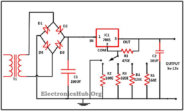
Working
- Bridge rectifier is used fr converting AC to DC.
- Then the voltage is applied to the 7805 voltage regulator.
- Output of the regulator can be varied by varying the resistance connected to the common pin of the 7805.
How to Calculate the Resistance Value for the Different Voltage?
Imagine that the resistor which is attached between the com terminal and the output terminal of regulator has a value of 470ohm (R1). This implies that the value of current is 10.6 mA (as V =5V furthermore V=IR) existing among com and output. Among the rotary switch and ground there is some amount of standby current of 2.5 mA approx.
Hence about 13.1 mA of overall current is available. Now assume that from the circuit we need 5V to 12V. With the regulator output we directly got 5V minimum. While if there is a need of 12V then between com and output 5V is available and for the rest 7V we need to select the appropriate value of the resistor.
Here R =?
V = 7V
I =13.1mA
Therefore V =I*R
R = 543ohm
Hence we have to attach resistor of 543 ohm with 470 ohm so to obtain the wanted output i.e. 12V. While it is difficult for us to get such a value of the resistor in the market so we can use the nearby value of the resistor i.e. 560ohm.
Now if we wish to have some other voltage from 5V to 12V then we have to attach some other value of the resistor.
Suppose we need 6V, then
V =6V
I = 10.6mA
R = 6V/10.6mA
R = 566ohm
But the resistor R1 is already on 470ohm which is already connected in the circuit, hence for 6V value of the resistor will be 100ohm approx (566-470=96). In the same manner for different voltages different value of resistance will calculated.
In spite of the different values of resistors variable resistor can be used in the circuit to get different value of voltage.
Related Article

10 Responses
Kindly provide the design of components use in the circuit.How the values are taken for the mentioned circuit
Grec ????? power supply 0-28v
Top circuit – R1 = 2k2 in series will cause a voltage drop going into the regulator. Draw more than 10mA and there will be no voltage left (2.2×10 = 22V). Works ok into a meter which doesn’t draw significant current. The 2k2 should be accross the smoothing capacitor to discharge it when the power is switched off
24V secondary will give 34V going into the regulator, It is rated at only 37V so not much margin…Then if you use it as a 12V 1A supply, you will dissipate (34-12)/1 = 22W so a big heatsink is essential
Under the portion where you show the 6-8A power circuit, do you have a value for C11? I didn’t see it on the parts list
Hi.Is the diagram of 6_8AMPER POWER supply safe about short circuit?
what does rv3 do on the 0-28V, 6-8A Power Supply Circuit Diagram using LM317 and 2N3055
Some idea of the size of heatsink required would be useful. “Huge” is a bit vague.
blows in total 6 of my 3055 and 2 of my lm 317 in the 6 to 8 amp circuit.
i think this circuit stinks.
it works for 2 minutes and than the voltage at the output is 42 volts and blows my led array twice.
pcb is checked out more than once and there is nothing wrong so it has to be the circuit.
Hi in the 6-8 amp circuit I am confused regarding the mains voltage being connected to the wrong sides of the rectifier causing the DC supply to be no DC, allowing for this and assuming the connections are made correctly, the question then is which line is pos. and neg. this is made more difficult as Capacitors Nos. C2, C3 and C10 are contradicting
Please could you clarify as this circuit would prove invaluable to me.
many thanks
The 6-8 amp circuit as drawn has many errors in it.
Ouch! Not good for the beginner!