This circuit protects the costly equipment like TVs, air conditioners, Refrigerators, etc. from high voltages as well as low voltages. If the supplied voltage is abnormal (High or low) then the circuit automatically turns of the load. This circuit also produces sound when main power resumes.
Generally voltage stabilizers are used in this type of applications to maintain constant AC voltage. However due to the abnormal AC supply, relays in voltage stabilizer switches ON and OFF continuously. The frequent energization or de-energization of relays leads to the shortening the life time of appliances and the stabilizer itself. Hence it is better to use this project in order to control the appliances instead of costly stabilizers.
Related Post: Variable Voltage Power Supply from Fixed Voltage Regulator
High and Low Voltage Cutoff with Delay and Alarm Principle:
When supply voltage is high, the DC voltage at the cathode of zener diode D4 becomes greater than 5.6V. As a result, transistor Q1 is in ON and transistor Q2 gets switched off. Hence the relay RL1 de-energizes and load would be in OFF condition.
Under low supply voltage condition, transistor Q1 switches to ON condition and as a result transistor Q2 switches off, making the load OFF.
When normal AC supply voltage is applied, the DC voltage at the cathode of zener diode D4 is less than 5.6V, now transistor Q1 is off condition. As a result, transistor Q2 is in ON condition, hence load switches to ON by indicating the green LED.
When supply is resumed after a break, 555 timer IC goes low and this triggers the 555 timer IC. The output of 555 timer IC makes sound IC to operate through the transistor Q3, at the same time, transistor Q1 switches to ON condition as the output 555 timer is connected to the base of Q1 and results transistor Q2 OFF. Thus the relay switches off the load.
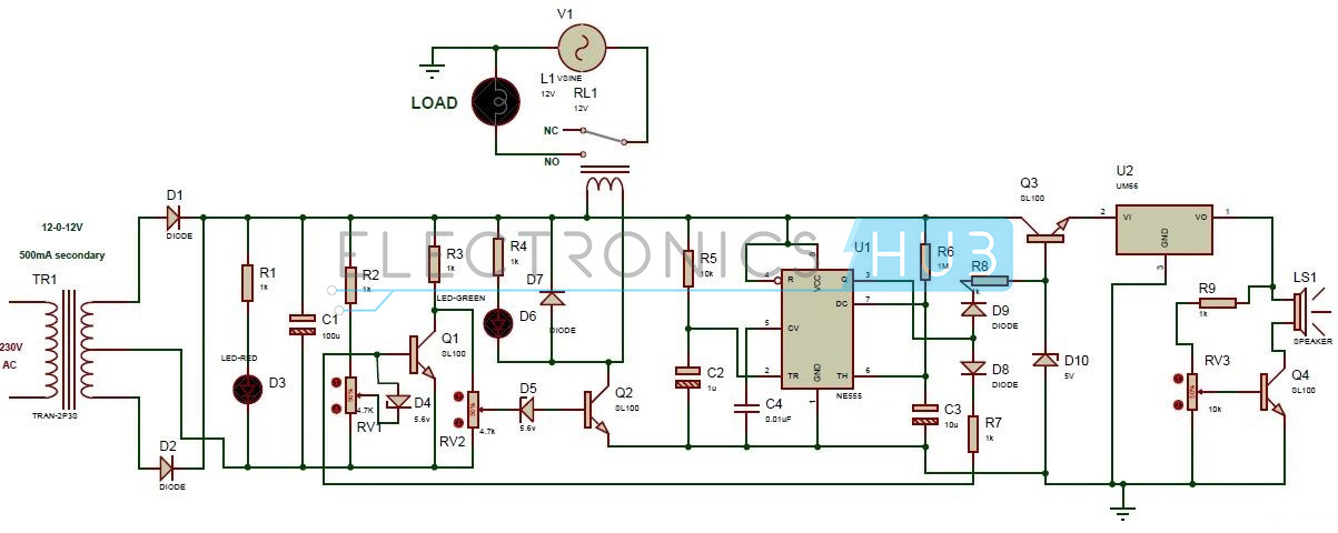
High and Low Voltage Cutoff with Delay and Alarm Circuit Diagram:
- Center tapped Transformer (12-0-12V, 500mA)
- NE 555 timer
- UM66 IC
- Speaker
- 12V Relay
- 4 Transistors – SL100
- 2 Zener diodes – 5.6V
- Zener diode – 5V
- LED’s – red, green
- 5 Diodes – 1n4001
- 16V Electrolytic capacitors – 100uF, 10uF, 1uF
- Ceramic capacitor – 0.01uF
- Potentiometers – 4.7k, 4.7k, 10k
- 7 Resistors – 1k
- Resistors – 10k, 1M
High and Low Voltage Cutoff with Delay and Alarm Circuit Design:
In this circuit, 555 timer is configured to operate in monostable mode. In this circuit, pin4 and pin8 are shorted to avoid sudden resets. The pulse width of the 555 timer output signal is about 10 seconds. This output signal drives the speaker.
Speaker gives melodious sound when power is resumed because of UM66 IC. The volume of the speaker can be controlled by using POT RV3.
Green LED indicates normal AC supply voltage. Red LED is used for power indication.
Here zener diode D4 along with transistor Q1 is used for comparing the input voltage. Transistor Q2 switches the load based on the output of transistor Q1. Diodes D1 and D2 are used for rectification purpose. Capacitor C1 filters the input AC ripples.
How to Operate this Circuit?
- Give the connections according to the circuit Diagram
- While giving the supply, make sure that there is no common connection between AC and DC supplies.
- Switch ON the input AC supply.
- Make the input supply voltage low or high. Now, you can observe that load is automatically switches off.
- Apply normal supply voltage. Now, you can observe that load will run by indicating the green LED.
- Now resume the power. You can listen melodious sound.
- Switch off the supply.
High and Low Voltage Cutoff with Delay and Alarm Circuit Advantages and Applications:
- Cost is less as compared to voltage stabilizers
- Consumes less power.
- This circuit is used in homes and offices to protect equipments from high voltages and low voltages.

14 Responses
In this circuit i cant able to understand why V1 vsine is connected to relay and what is vsine.
please help me to submit this mini project on coming saturday.
Thank you for providing us a good way of knowledge.we are just come to electronics field and we used this informations.
what is power resume? and how to resume power in operation
Hello… Pls can u upload a schematic diagram of a transformerless 2KVA avr… Thanks
Thank you for the providing this knowledge…….
What is use of variable resistors here?
Circuit is not cutting off when a high input voltage is applied.please help
Alternative to SL100 ???
BD 139
High and low voltage cutoff circuit is working.but buzzar not working.can you please explain how and when the buzzar sounds?
pls can u tell me how can u reduce or increase your voltage??by potentiometers or another regulator.
Green led not turning off when input voltage is high.why?
Please help
What is resume power. can anyone explain?
Wat is resume power can anyone explain?