Introduction
In this tutorial, we will see about one of the most commonly used regulator IC’s, the 7805 Voltage Regulator IC. A regulated power supply is very much essential for several electronic devices due to the semiconductor material employed in them have a fixed rate of current as well as voltage. The device may get damaged if there is any deviation from the fixed rate.
One of the important sources of DC Supply are Batteries. But using batteries in sensitive electronic circuits is not a good idea as batteries eventually drain out and loose their potential over time.
Also, the voltage provided by batteries are typically 1.2V, 3.7V, 9V and 12V. This is good for circuits whose voltage requirements are in that range. But, most of the TTL IC’s work on 5V logic and hence we need a mechanism to provide a consistent 5V Supply.
Here comes the 7805 Voltage Regulator IC to the rescue. It is an IC in the 78XX family of linear voltage regulators that produce a regulated 5V as output.
A Brief Note on 7805 Voltage Regulator
7805 is a three terminal linear voltage regulator IC with a fixed output voltage of 5V which is useful in a wide range of applications. Currently, the 7805 Voltage Regulator IC is manufactured by Texas Instruments, ON Semiconductor, STMicroelectronics, Diodes incorporated, Infineon Technologies, etc.
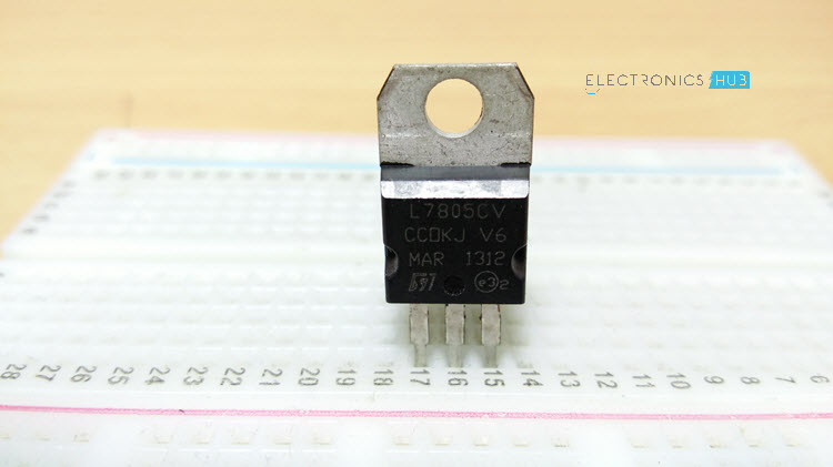
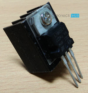
They are available in several IC Packages like TO-220, SOT-223, TO-263 and TO-3. Out of these, the TO-220 Package is the most commonly used one (it is the one shown in the above image).
Some of the important features of the 7805 IC are as follows:
- It can deliver up to 1.5 A of current (with heat sink).
- Has both internal current limiting and thermal shutdown features.
- Requires very minimum external components to fully function.
Pin Diagram of 7805 Voltage Regulator IC
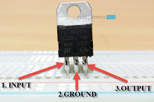
As mentioned earlier, 7805 is a three terminal device with the three pins being 1. INPUT, 2. GROUND and 3. OUTPUT. The following image shows the pins on a typical 7805 IC in To-220 Package.
The pin description of the 7805 is described in the following table:
Pin 1 is the INPUT Pin. A positive unregulated voltage is given as input to this pin.
Pin 2 is the GROUND Pin. It is common to both Input and Output.
Pin 3 is the OUTPUT Pin. The output regulated 5V is taken at this pin of the IC.
Basic Circuit of 7805
As I have previously talked about regulated power supply as a device that works on DC voltages and it can uphold its output accurately at a fixed voltage all the time even if there is a significant alteration in the DC input voltage.
As per the datasheets of 7805 IC, the basic circuit required for 7805 to work as a complete regulator is very simple. In fact, if the input supply is an unregulated DC Voltage, then all you need are two capacitor (even those are not mandatory depending on the implementation).
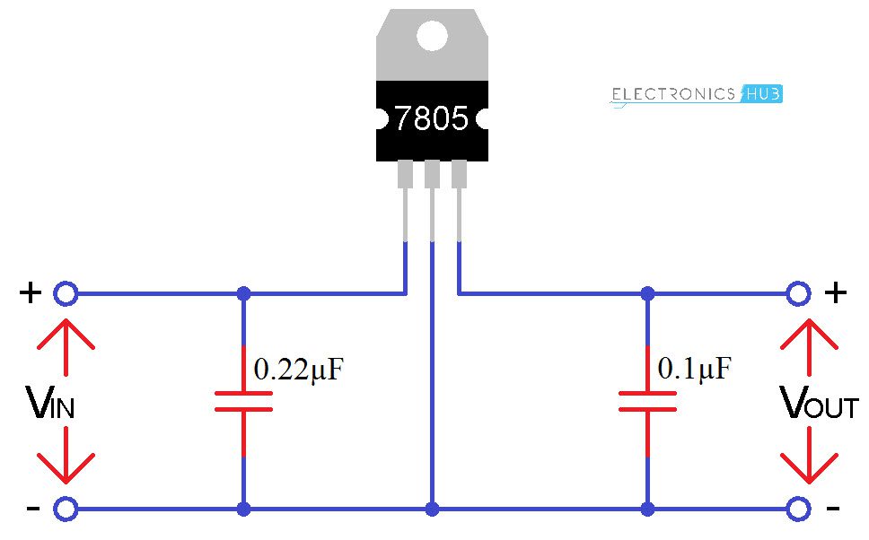
The above circuit shows all the components required for a 7805 IC to work properly. The 0.22μF Capacitor near the input is required only if the distance between the regulator IC and the power supply filter is high. Also, the 0.1μF Capacitor near the output is optional and if used, it helps in the transient response.
In this circuit, VIN is the input voltage to the 7805 IC and the source can be from either a battery of an unregulated DC. VOUT is the output of the 7805 IC, which is a Regulated 5V.
How to Get Constant DC Power Supply from AC?
Although batteries can be used as input to the 7805 Voltage Regulator IC, we face certain bumps like frequent discharge of batteries and reduction of battery voltage levels over a period of time.
The best alternative to using Batteries is to provide an unregulated but rectified DC Voltage from an AC Source. Since AC Source is easily available as mains supply, we can design a circuit to convert AC Mains to DC and provide it as input to the 7805 Voltage regulator IC.
Circuit Diagram
The following image shows the circuit diagram of producing a regulated 5V from AC Mains supply.

Components Required
- 230V-12V Step Down Transformer
- Bridge Rectifier (or 4 PN Diodes – 1N4007)
- 1A Fuse
- 1000μF Capacitor
- 7805 Voltage Regulator IC
- 0.22μF Capacitor
- 0.1μF Capacitor
- 1N4007 Diode
[Also Read: How To Make an Adjustable Timer ]
Working
The AC power supply from mains first gets converted into and unregulated DC and then into a constant regulated DC with the help of this circuit. The circuit is made up of transformer, bridge rectifier made up from diodes, linear voltage regulator 7805 and capacitors.
If you observe, the working of the circuit can be divided into two parts. In the first part, the AC Mains is converted into unregulated DC and in the second part, this unregulated DC is converted into regulated 5V DC. So, let us start discussing the working with this in mind.
Initially, a 230V to 12V Step down transformer is taken and its primary is connected to mains supply. The secondary of the transformer is connected to Bridge rectifier (either a dedicated IC or a combination of 4 1N4007 Diodes can be used).
A 1A fuse is placed between the transformer and the bridge rectifier. This will limit the current drawn by the circuit to 1A. The rectified DC from the bridge rectifier is smoothened out with the help of 1000μF Capacitor.
So, the output across the 1000μF Capacitor is unregulated 12V DC. This is given as an input to the 7805 Voltage Regulator IC. 7805 IC then converts this to a regulated 5V DC and the output can be obtained at its output terminals.
Important Points on 7805 Voltage Regulator IC
- The first important point to note is that the input voltage should always be greater than the output voltage (atleast by 2.5V).
- The input current and output current are almost identical. This means that when a 7.5V 1A supply is given at input, the output will be 5V 1A.
- The remaining power is dissipated as heat and hence a heat sink like the one shown below must be used with 7805 IC.
Also read the related post: Variable Voltage Power Supply from Fixed Voltage Regulator

42 Responses
Wow, thіs post is good, my sister is analуzing these things, so I am going to tell her.
Wow this is interesting
This is very ezy mathad for making Mobil charger .
it’s best way to supply voltage to voltage device
I AM HAPPY WITH YOUR EXPLANATION BUT I HAVE ONE DOUBT . ON WHAT BASIS YOU ARE CHOOSING THE CAPACITOR VALUE . PLEASE GUIDE ME .
Manufacturer Data Sheet has minimum values, higher current draw would require higher value capacitors.
one of the best website for mini projects. it has some unique ideas based on mini projects related to electronics engineering.
what is the amperage in the above circuit?
ampere depend upon your transformer
If you try to draw more than 1 AMP then the fuse should blow eventually.
Oozam.but pls help me that which device it is founded so I can take from that if I have can u pls tell me
Radio
super
What is the input voltage rating in this 7805 ic?
7 V to 20 V
I think its 7 to 35 Volts?
In votage regulated ckt, i want to output 30 volt then what we have change in this circuit?
Not with this circuit, 12 to 30 V not possible with a 7805. Best to start with a clean sheet.
i made this but it take many time to charging any phond.because it’s mah is low.so what i do for increase voltage amphere.
Increase the T1 value from 500ma to 1 amp
wow! it’s very interesting.
Nice info this helped me in my project file of 12 th board practicals.
Hello, this stduy is very clear and easy to understand, thank you. I wonder that I try to design a PCB including a microcontroller (ie. ATMEL328P) I will use voltage regulator, but how can I determine the value of components such as capacitor or resistor if I need. I want to supply microcontroller ATMEL328P-AU. Also, I need help that why we need bypass capacitors for crystal oscillator which will be used for the microcontroller. How can I determine the capacitor values.
How can I use 7805 transistor on 12v DC supply?
7812 regulator is for +12V so you can use it instead of 7805.
78(05) = +5V DC
78(12) = +12V DC
79(05) = -5V DC
79(12) = -12V DC
Of course you can but the output will be 5v
Waoo this very helpful
Great detail mate.
Ill share this one.
Thank you.
why is 1000 microfarad specifically used after bridge rectifier? what is the calculation for that?
Just search “calculating smoothing capacitor values” . The Bridge rectifier output will still have a varying DC value this capacitor helps to remove or reduce this value, Smooth out the waveform.
this is a very good training to me
Hello,may I ask something?
With the same circuit can I get output 5V 2A?
Use transistor as amplier or they have another way?
Dear
The IC7805 circuit can provide only MAx 1.5 Amps of current with 5volt.
Easiest way to get 2 Amps would be use the output of the 7805 to drive a Power mosfet with low switch on voltage.
how can we change the output voltage?
Depends what voltage , might be easiest to use a different regulator. You could change the output by changing the voltage on pin 2 from 0v to something else, eg put a diode from pin 2 to earth, the output will be approx 5.7v
intresting,, thank you for the ideas
Whay is there a 1N4007 diode at the end of the circuit ?
Very clear and understandable…. Thanks very much you have boost my knowledge alot.
which IC form the 78XX series should i choose to get a output current of 500mA.also will the circuit for the
IC will be the same a this or need to make some changes
what happens when the input is less than the output??