In this tutorial, we will learn about one of the important concepts for any hardware / system designer: A Low Drop Out Regulator or an LDO. We will see what an LDO is, understand how a low drop out voltage regulator works, important characteristics of LDOs and also a few parameters.
The size of modern electronic devices is ever decreasing. But the battery efficiency figures are changing that much which is a factor for pushing the limits on power management systems.
Technical developments in semiconductor manufacturing has led to SoC or System on Chip architecture, where analog, digital and RF subsystems are integrated into a single silicon die. This means that different blocks of the system have different power supply requirements.
A power management system (PMIC) contains several power supply circuits like switching regulator, DC-DC Converter, linear voltage regulator and an LDO. We will concentrate on LDOs in this tutorial.
Read TYPES OF VOLTAGE REGULATORS
What is an LDO?
A Low Drop out Voltage Regulator or simply an LDO Regulator is an essential part of power management system particularly in battery operated devices. LDOs can provide multiple voltage levels with a constant and stable output. The output voltage of an LDO is independent of the load impedance, the changes in the input voltages (discharge in battery) and temperature.
LDO regulator or Low-dropout regulator is a type of linear voltage regulator which can operate at very low potential difference between the input and the output. For example, a typical Li-ion battery has a range of 4.2 V at fully charged to 2.7 V at fully discharged. Even when the battery voltage is below 3 V, an LDO can still maintain the desired 2.5 V at the output.
Brief note on Linear Voltage Regulators
You might have seen / used several Linear Voltage Regulator ICs in your circuit design. If you are a beginner or a hobbyist in electronics, then you should have come across the renowned 78XX series of voltage regulators like 7805 or 7812, for example. These are examples for Linear Voltage Regulators.
A Linear Voltage Regulator is a device or a circuit with a variable input voltage and a steady, continuously controlled, low-noise DC output voltage. The constant output voltage of a voltage regulator is a result of continuous adjustment of its internal resistance with respect to the changes in the load resistance.
Linear Voltage Regulators Schematic Diagram

The output voltage of this simple constant voltage regulator is given by the following equation:
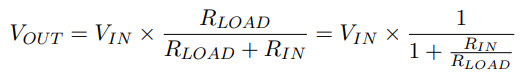
If any load is absent i.e. RLOAD = ∞, the output voltage is maximum and is equal to the input at the voltage regulator. In the presence of a load, the output voltage will be less than the maximum possible value. The difference between the maximum output voltage and output voltage with load is called the output voltage error represented by EVO.
This error is usually represented as percentage difference between maximum output voltage and output voltage with load.
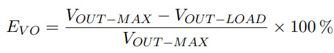
In terms of input and load resistances, the error percentage is given by:

We need to minimize this error and in order to do that, we need to introduce a feedback. The feedback circuit will sense the changes occurring in the load and adjusts the variable internal resistance so that the ratio of internal resistance to load resistance will remain constant.
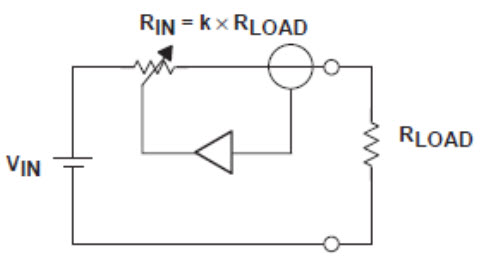
From the above assumption, we can say that internal resistance is following the load resistance in a “Linear” fashion.
Understanding Low Drop Out Regulator
We can categorize linear voltage regulators into two types: Standard or Basic Voltage Regulators and low drop out regulators. The main difference between the two is the amount of dropout voltage and type of pass element used.
The dropout voltage, also known as the amount of headroom, is the minimum voltage across the regulator for proper regulation. The output voltage is equal to the difference between the input voltage and the voltage drop across the pass element.
In case of standard linear regulators, the pass element is a Darlington pair of either NPN or PNP. They have been replaced by MOSFETs in modern designs.
Coming to Low Dropout Regulators, the voltage drop across the pass element is usually very less for the regulator to properly regulate the input voltage.
The following Low Drop Out Regulator schematic diagram shows a classic layout of an Low Dropout Voltage Regulator. It consists of a pass element, an error amplifier and a resistor feedback network.
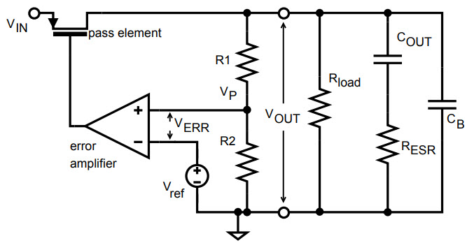
The resistive feedback network, consisting of a voltage divider, will provide a scaled output voltage equal to the reference voltage. The error amplifier constantly compares the reference voltage and the feedback voltage (provided by voltage divider).
It then amplifies the difference and the output will drive pass element (MOSFET) to keep the output voltage at the desired level.
Elements of LDO Regulator
Let us no take a closer look at all the elements of an Low Drop Out Regulator.
Voltage Reference
It is the starting point of any regulator as it sets the operating point of the error amplifier. Usually, a band-gap type voltage reference is used as it allows to work at low supply voltages.
Error Amplifier
The main requirement in the design of the error amplifier is that it should draw as minimum current as possible. The output resistance of the amplifier must be as low as possible as the gate capacitance of the pass transistor will be large.
The output voltage scaled down by the voltage divider network is one input of the error amplifier while the other input is the reference voltage. After comparison, the error amplifier then adjusts the resistance of the pass element.
Feedback
The resistive voltage divider feedback is responsible for scaling down the output voltage and allows it to be compared with the reference voltage by the error amplifier.
Pass Element
The pass element in the LDO is responsible for transferring current from input to load and is driven by the error amplifier in the feedback loop. MOSFETs (both PMOS and NMOS) are generally used as pass elements.
The following image shows a typical LDO layout with PMOS pass element.
VGS of the PMOS pass element is tied to Vdd. The minimum voltage required by the PMOS transistor to stay in saturation and regulate properly is given by the minimum drain source voltage Vds. PMOS Pass Element is not suitable for very low voltage applications.
NMOS Pass Element based LDO is shown in the following image. The advantage of NMOS is that it is in source follower configuration and the output of the regulator is at the source of the transistor.
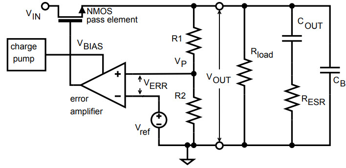
The circuit using NMOS transistor is usually large and complex but it is possible to achieve low input, output and dropout voltage.
Output Capacitor
The output capacitor is an important component in an LDO Regulator as it ensures that the current is delivered immediately to the load during load transients until the error amplifier is ready.
ESR or Equivalent Series Resistance of the capacitor is very important as it restricts the current flow from capacitor to the load. Hence, for a 1µF capacitor with ESR in the range of 10mΩ to 300mΩ, the possible capacitor types are:
- Ceramic Capacitors
- Polymer Electrolytic Capacitors
- Low-ESR Tantalum Capacitors
LDO Parameters
Now, let us take a look at some of the important steady state and transient parameters of a Low Dropout Voltage Regulator.
Dropout Voltage
The difference between the input and output voltages of the regulator is called as the Dropout Voltage of the regulator. If the input voltage approaches the output voltage, the regulator ceases to regulator.
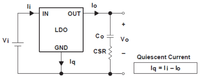
Quiescent Current
The difference between the input current and output current is known as Quiescent Current or Ground Current. In low power systems, a low quiescent current will lead to maximum efficiency.
Efficiency
The efficiency of an LDO Regulator is dependent on the quiescent current and input to output voltage. Efficiency is given by:
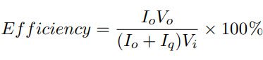
By minimizing the dropout voltage as well as the quiescent current, the efficiency of LDO can be increased.
Transient Response
It is the maximum output voltage variation for a load current step or input voltage step. Transient response is a function of the output capacitor with its ESR (equivalent series resistance).
Line Regulation
Line Regulation is the ability of the regulator to maintain the desired output voltage with varying input voltages.
Load Regulation
If the demand for load current increases, then the output capacitor is responsible for supplying the current. As a result, the output voltage is changed, which is sensed by the feedback network.
To compensate this, the error amplifier passes more current to flow through the pass transistor. Load Regulation is the ability of a regulator to maintain the desired output voltage in spite of varying load currents.

One Response
Hi, i want to ask help about my bachelor thesis about the simulation of power supply for IoT sensor nodes
i will simulate with LTSpice
– i want to have help also about simulation of voltage regulator
Thank you