Fire Alarm Circuit is a simple circuit that detects the fire and activates the Siren Sound or Buzzer. Fire Alarm Circuits are very important devices to detect fire in the right time and prevent any damage to people or property.
Fire Alarm Circuits and Smoke Sensors are a part of the security systems which help in detecting or preventing damage. Installing Fire Alarm Systems and Smoke Sensors in commercial buildings like offices, movie theatres, shopping malls and other public places is compulsory.
Simple Fire Alarm Circuits at Low Cost
There are many expensive and sophisticated Fire Alarm Circuit in the form of stand-alone devices, but we have designed five very simple Fire Alarm Circuits using common components like Thermistor, LM358, Germanium Diode, LM341 and NE555.
We will see all these circuit, their circuit diagrams, components required for each circuit and the working of the individual circuit in the following sections.


Circuit 1 Simple Fire Alarm Circuit
This is a very simple alarm circuit using Thermistor, LM358 Operational – Amplifier and a Buzzer.
Circuit Diagram
The circuit diagram of this simple Fire Alarm Project is shown in the following image.

Components Required
- 1 x 10 K Thermistor
- 1 x LM358 Operational Amplifier (Op – Amp)
- 1 x 4.7 KΩ Resistor (1/4 Watt)
- 1 x 10 KΩ Potentiometer
- 1 x Small Buzzer (5V Buzzer)
- Connecting Wires
- Mini Breadboard
- 5V Power Supply
Component Description
10K Thermistor
Thermistors are Temperature Dependent Resistors i.e. the resistance of a Thermistor varies according to the ambient temperature. There are two types of Thermistors: PTC Thermistor and NTC Thermistor. PTC stands for Positive Temperature Coefficient and NTC stands for Negative Temperature Coefficient. In PTC Thermistor, the resistance is directly proportional to the temperature and in NTC Thermistor, the resistance is inversely proportional to the temperature.
In this project we have used a 10 KΩ Thermistor with NTC. At 250C, the resistance of the 10 KΩ Thermistor is 10 KΩ. The following image shows the 10K Thermistor used in this project.

LM358 Operational Amplifier
LM358 is a Dual Operational Amplifier (Op – Amp) IC. All the functional modes of the typical operational amplifier can be implemented using LM358 IC. In this project though, we will be using the LM358 Operational Amplifier in the Comparator Mode where the input signals on inverting and non – inverting terminals are compared and corresponding output is produced.
Circuit Design
The design of the Fire Alarm Circuit with Siren Sound is very simple. First, connect the 10 KΩ Potentiometer to the inverting terminal of the LM358 Op – Amp. One end of the POT is connected to +5V, other end is connected to GND and the wiper terminal is connected to Pin 2 of Op – Amp.
We will now make a potential divider using 10 K Thermistor and 10 KΩ Resistor. The output of this potential divider i.e. the junction point is connected to the non – inverting input of the LM358 Operational Amplifier.
We have chosen a small, 5V buzzer in this project to make the alarm or siren sound. So, connect the output of the LM358 Op – amp to the 5V Buzzer directly.
Pins 8 and 4 of the LM358 IC i.e. V+ and GND are connected to +5V and GND respectively.
Working of the Simple Fire Alarm Circuit
We will now see the working of the simple Fire Alarm Circuit. First thing to know is that the main component in detecting the fire is the 10 K Thermistor. As we mentioned in the component description, the 10 K Thermistor used here is a NTC type Thermistor. If the temperature increases, the resistance of the Thermistor decreases.
In case of fire, the temperature increases. This increase in temperature will reduce the resistance of the 10 K Thermistor. As the resistance decreases, the output of the voltage divider will increase. Since the output of the voltage divider is given to the non – inverting input of the LM358 Op – Amp, its value will become more than that of the inverting input. As a result, the output of the Op – Amp becomes high and it activates the buzzer.
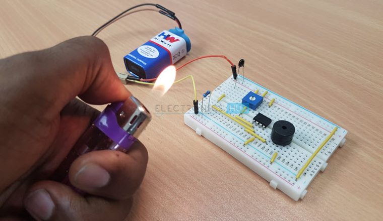
Circuit 2 Simple Fire Alarm Circuit using Thermistor
Circuit Diagram
Components of Fire Alarm Circuit
- Thermistor
- Variable resistor(POT)
- Diode
- Capacitor
- Resistor
- BC547 Transistor
- Speaker
Circuit Working
- The circuit consists of a 10k ohm thermistor. This is an NTC thermistor, which decreases its resistance with increase in the temperature.
- At room temperature it had a resistance of 10kohms.
- Another resistance is connected to the thermistor to form voltage divider circuit and this is connected to the transistor through a diode.
- Buzzer switches on only when the transistor is grounded. As the temperature increase the buzzer sound also increases
Also read this interesting post: Panic Alarm Circuit
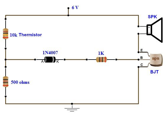
Circuit 3 Fire Alarm with Siren Sound
This circuit alerts us when there is a fire accident at home by ringing a siren sound. You might have seen fire alarms earlier but this is quite different as it generates a siren sound instead of a buzzer and also it uses basic components to generate that siren sound.
We are aware that there are many integrated circuits which can be used to generate the siren effect but we preferred to use basic electronics components like resistors, capacitors and transistors to generate it so that you will clearly understand the internal working of it and it will be much useful for you as you will gain more knowledge by analyzing it instead of simply going for pre designed integrated circuits.
Circuit Diagram
Components Required
- 1 x 10K Thermistor
- 2 x BC547 NPN Transistor
- 1 x BC107 NPN Transistor
- 1 x 2N2222 NPN Transistor
- 1 x 2N2907 PNP Transistor
- 3 x 4.7KΩ Resistor (1/4 Watt)
- 1 x 470KΩ Resistor (1/4 Watt)
- 1 x 56KΩ Resistor (1/4 Watt)
- 1 x 47KΩ Resistor (1/4 Watt)
- 1 x 39KΩ Resistor (1/4 Watt)
- 1 x 22KΩ Resistor (1/4 Watt)
- 1 x 1KΩ Resistor (1/4 Watt)
- 1 x 470Ω Resistor (1/4 Watt)
- 1 x 120Ω Resistor (1/4 Watt)
- 1 x 10KΩ Potentiometer
- 1 x 22µF Capacitor (Polarized)
- 1 x 470nF (0.47µF) Ceramic Capacitor
- 1 x Buzzer
Working
This circuit uses a thermistor to sense the temperature. When it senses that the temperature of the environment is increasing above a given threshold, then it gives a signal. The temperature at which the circuit detects fire can be adjusted by using the potentiometer arrangement at VR1.
Get an idea about Thermistor Temperature Sensing Alarm if you are interested.
When the temperature increases above the set value, the potentiometer arrangement produces a high voltage. This voltage is then given to BC547 transistor in common emitter mode. It is an NPN general purpose transistor. When the base is given a high input, it gets turned on. When the transistor is turned on, its collector voltage is reduced to low as the collector to emitter voltage decreases. The collector output voltage of the first transistor is given to the base as an input to the second BC 547 NPN transistor. This transistor too is in common emitter mode and as the input is low when the temperature threshold is reached, the output at the collector will rise high. In this state, it will turn on the next transistor, i.e. BC107. This transistor will now act as a switch for the siren circuit. This transistor can bear power quite larger than the BC547 and it is also equipped with a heat sink for that purpose.
When the BC107 transistor turns on, it allows current to pass from power supply to ground through collector thereby acting as an electronically controlled switch. When the current is passing, the siren circuit which is assembled as the load to the circuit is turned ON. Then you can hear the siren sound through the buzzer. The capacitors used in the circuit are the main components in producing the siren effect. The principle involved in generating the siren effect is to make an oscillator with an envelope which periodically increases and decreases so as to generate that effect.
Related Post: Pull Pin Security Alarm Circuit
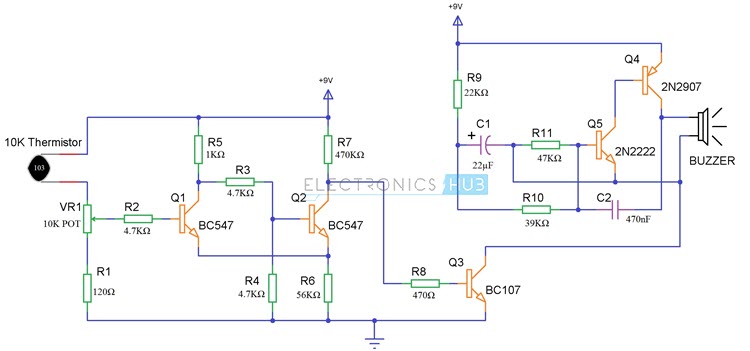
Circuit 4 Fire Alarm Circuit Using LM741
Here is another small project on fire alarm. When a fire accident is happened in home or office, it will detect the fire and give the alarm.
Block Diagram of Fire Alarm Circuit Using LM741
The thermistor is the main component which detects the fire by sudden change in the room temperature because of the heat generated by the fire. The thermistor will detect the heat and give the information to the LM741 OP-AMP. The op-amp will make the NE555 to generate pulse which has been given to a buzzer to buzz.
LM741: LM741 is an operational amplifier which will work according to the difference in the input voltages. LM741 has following features like high current driving, voltage gain, noise amplification and also provide low output impedance. LM741 can also use as a short circuit protection.
Circuit Diagram of Fire Alarm Using LM741
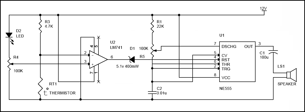
Circuit working
- Circuit principle is similar to the first circuit i.e. Thermistor is used to sense the raise in temperature. But it rises only after a fixed temperature.
- Here op amp acts as non-inverting comparator i.e. Vout is positive only if Vin (voltage at pin 2) < VRef (voltage at pin3).
- When there is no any fire, voltage at pin 2 of the comparator is greater than the voltage at pin3.
- When there is no fire resistance of thermistor is 10k. So 10K and 4.7k forms voltage divider circuit.
- Voltage at pin2 is calculate using formula. V= (100*12) / (100+4.7) =11.4
- Voltage at pin 3 =50*12/100=6v (Variable pin of the pot is at 50% of total resistance.)
- When there is any fire thermistor temperature raises and its resistance decreases. So voltage at pin2 starts decreasing. Thus Vout is goes to positive i.e. it is equal to Vcc.
- Here reference voltage selected is 6v.Fire alarm starts only if the input voltage is less than 6v.To increase the reference voltage decrease the resistance of pot.
Circuit 5 Fire Alarm Circuit Using Germanium Diode
This is a simple fire alarm circuit using Germanium Diode and 555 timer. In this circuit Germanium Diode play very important role in detecting the fire. This circuit is very easy to construct, cost effective and implementable.
Block Diagram of Fire Alarm Circuit Using Germanium Diode

Here is the simple fire alarm circuit which costs less than 100 rupees. The key component in the circuit is DR25 (germanium diode) whose resistance will decrease with increase in temperature. The conduction of germanium diode will start at 70 degrees. So we may use germanium diode as a heat sensor. When the temperature is more than 70 degree, the germanium diode will conduct and trigger the NE555 timer through a transistor. The NE555 is configured in astable Multivibrator and make the buzzer to alarm when germanium diode conducts. So that we can get alert and act according to the alarm.
Circuit Diagram of Fire Alarm Using Germanium Diode
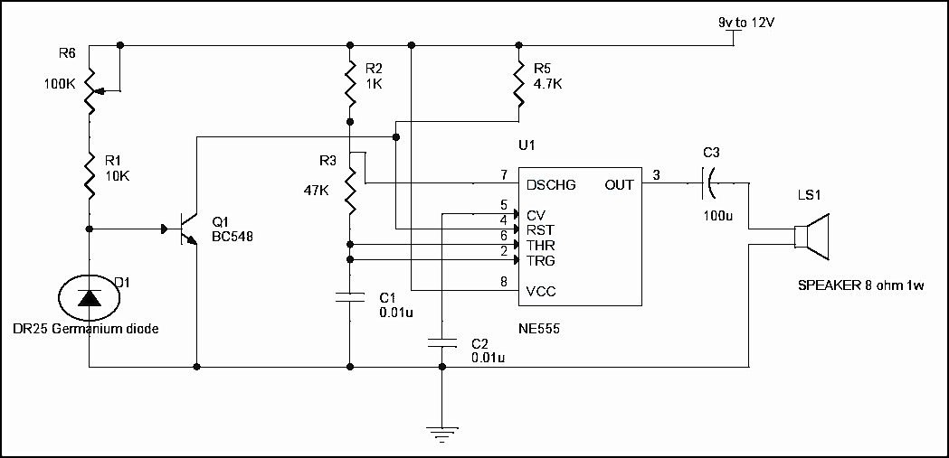
Circuit Working
- The DR25 germanium diode is heat sensor which will conduct when temperature is increased at certain point. The DR25 is made reverse biased in the circuit. It will conduct only when it is more than 70degree of room temperature.
- The DR25 is connected to the transistor in reverse bias, which has high reverse resistance (more than 10K ohm) and does not make the transistor to turn off which is connected to the reset pin of 555 timer. The reset pin of 555timer will be in ground level when the transistor is turned off. Here, the 555 timer is configured as astable Multivibrator.
- When more than 70degrees in room temperature occurred, the resistance of DR25 diode drops to 1k ohm which will make the transistor to turn off and make the reset pin to go high. This will generate the output at pin3 and make the sound through the alarm.
- We can use 3 or more diodes in reverse bias connected in parallel and placed in different room. If there is fire accident, it will sense and make the alarm.
Note
-
- If DR25 germanium diode is available, you can still use AC128, AC188 or 2N360 germanium transistors. Use base and emitter junctions in place of cathode and anode.
- Diode must be connected to the circuit in reverse bias.
Applications
- Fire Alarm Circuits are very useful in homes, offices, schools, labs, etc. to detect and prevent any disasters due to fire.
- Fire Alarm Systems can work as a stand – alone devices or be a part of a complex home security system with other security features like smoke detection, intruder alert, motion detection, etc.

18 Responses
Was looking for circuit like this , its nice , really helpfull
thank you very much for these circuits
they were very helpful
the connection for ne555 is it correct??? i try to build this circuit but can’t work!!
It is already verified and is working very fine. Once again please check your circuit connections.
Plz tell me where is capacitor used in “simple low cost fire alarm ckt”
WHY DOES GROUND AND IN A+ HAVE THE SAME CONNECTION
It doesn’t? Not sure where you see that at.
It is actually a nice and useful piece of info.
I’m satisfied that you just shared this useful info with us.
Please stay us informed like this. Thanks for sharing.
Thanks alot. This curcuit will help me very well
Hey, I’m using Proteus to make this, what’s the default resistance of the thermistor should I use?
provide value of thermister plz!
It is provided. All of these that have the thermistors are 10K, as stated in either the parts list or in the diagram itself.
Please explain the use of registers in fire alarm ckt using germanium diod
Anyone suggest me a simple mini project with output to be submitted within two days
thanks for great work of providing us those circuits!!!! so, on fire alarm using LM741, Sir What is exactly temperature the thermistor working on(sensing)
Tnq vry much…
The fire alarm with siren sound is not working, have tried it. Why? Please I need it for my school project.
How many cost sir in this circuit