This circuit helps us to get alerted when anybody picks our pockets or bags. The circuit is very helpful to prevent our goods getting pick pocketed. The circuit is called a pull pin security alarm circuit because it gets activated as soon as the pin is pulled.
Pull Pin Security Alarm Circuit Diagram:
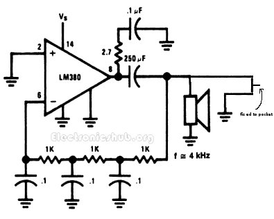
Components Required:
- LM380
- Resistor 1k -3
- Capacitor 0.1uF-4,250uf-1
- Speaker-1
Description:
The arrangement of the circuit is as follows. The circuit has a pin which is fixed to the pocket and the other end is attached to the circuit. The circuit remains inactive until the wallet is in your pocket as the circuit gets activated when the wallet is pulled from your pocket.
When the wallet is in the pocket, the circuit has the pin attached thereby the circuit remains inactive. Whereas when the wallet is removed from the pocket, the pin gets detached from the circuit thereby the circuit gets activated. When the circuit gets activated, the circuit turns ON the mini loudspeaker. The mini loudspeaker is fed with an alternating signal of audio frequency. This signal vibrates the loud speaker at an audio frequency so that it is well heard to us.
Related Post: Luggage Security Alarm Project using Logic Gates
This can also be used to protect our purses, carry bags, and any other things. The applications of this are not just limited to this but there can be many other applications which you may get on imagining and when you face a problem. The circuit is made to be portable in size so that it can be carried easily with us. It uses a battery power supply.
The main component of the circuit is an oscillator which generates a sine wave of definite frequency. The oscillator which is used is an RC phase shift oscillator which produces the sine wave of definite frequency. The frequency of the RC phase shift oscillator is determined by the three stages of resistance and capacitance. Each stage of the resistor capacitor circuit consists of a resistor of 1 K-ohm and a capacitor of 0.1uF. Each of these RC stages theoretically produce a value of 90 degrees phase shift but practically they produce a phase shift lesser than that. In general, they are expected to produce a phase shift of about 60 degrees practically. That is why we have placed three such similar RC stages each of which produce about 60 degree phase shift and thereby combinedly produce a phase shift of 180 degrees. The amplifier circuit produces an additional phase shift of about 180 degrees. So, the total phase shift of the loop is the combination of phase shifts of the phase shift offered by the amplifier as well as the phase shift offered by the three RC stages which combinedly amounts to 360 degree phase shift. As you all know, this is one of the criterion’s of Barkhausen criterion’s for the circuit to function as an oscillator. The circuit should be provided a voltage of about 6V power supply.
The loud speaker which is used as a load at the output generates sound in audio frequencies. It is a mini loud speaker with an internal resistance of about 8 ohms. When the circuit is activated, the signal from the audio oscillator is fed to the mini loud speaker which then generated a beep sound of that specific audio frequency.
Also Read:

20 Responses
I need the details about this project
I need some more details
i need more details regarding this project
It works fine when the power is turned on and the switch is open. But if the switch is closed once, the oscillator does not start when the switch is opened again. Does anyone have any clues about how to fix this?
how if the person itself take out his/her wallet? will the alarm still functioning? how to prevent this?
Is it possible for you to add a parts list? It would be extremely helpful
how if the person itself take out his/her wallet? will the alarm still functioning? how to prevent this?and i need the image of the circuit model.
We have to take the circuit along with it
I need more details on this project. Can we replace some elements: capacitor 250mF with 220mF and op.amo 301?
we need more details
Could you please send component details
Can someone please show me, how to implement this in Logism application
I need still more details about it…. How the pull pin mechanism happening that and all… I want to know
can we replace lm380 with lc 741 will it work?
No.
simple project is easy to maintain and help full
How it is attached with the wallet
can we replace another amplifier instead of LM380N amplifier
I have a question..
Why does the alarm ring when the pin is pulled…like can you give a detailed working of it?
In simple…..this circuit is active all the time. which means the buzzer receives 4khz signal all the time when we power on the circuit. to avoid it, we used a key which is connected to the ground. So that the buzzer won’t receive the signal due to its resistance.