A burglar alarm system is designed to detect an unauthorized entry into a house or area. Burglar alarm systems can be used in residential buildings, commercial buildings, offices, industries and even in military locations.
Most of the home security systems are very expensive. With the help of this project, an inexpensive burglar alarm system can be implemented.
How To Make Best Burglar Alarm Circuit?
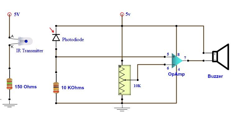
Circuit Diagram
Components Required
- LM358 – 1
- IR Transmitter or IR LED – 1
- Photo Diode – 1
- 10 KΩ – 1
- 150Ω – 1
- 10 KΩ POT – 1
- Buzzer – 1
Component Description
LM358
It is a dual Op Amp IC. It consists of two independent operational amplifiers that can be used separately. It is commonly used in all op amp circuits, transducer amplifiers, active filters, general signal conditioning and DC gain blocks.
IR Transmitter
Infrared or IR is a range of light frequencies that have longer wavelength than visible light. Hence, they are not visible to human eye. An IR transmitter or IR LED is a device that emits infrared light.
Photo Diode
A photo diode is a device that converts light to electrical current. It is basically a PN junction that operates in reverse bias condition. When light falls on the photo diode, a reverse bias current flows in the junction that is proportional to the luminescence of the light.
Buzzer
It is an alarming device that makes a loud sound when current flows through it.
Circuit Design of Burglar Alarm System
The IR transmitter or IR LED is connected to a current limiting resistor of 150Ω and connected to supply. It is placed at the maximum possible range from photo diode.
The cathode of the photo diode is connected to supply while anode is connected to 10KΩ resistor. Other end of the resistor is connected to ground. The anode terminal of the photo diode is also connected to pin 5 of LM358 op amp, which is the non-inverting terminal.
Wiper of the 10KΩ POT is connected to the inverting terminal i.e. pin 6 of LM358 while the other two terminals of the POT are connected to Vcc and ground.
Pins 8 and 4 of LM358 are supply pins. They are connected to Vcc and ground respectively.
The output of the op amp is taken at pin 7. One terminal of the buzzer is connected to pin 7 of LM358 while the other terminal is connected to Vcc.
Working
The aim of this project is to implement a simple Burglar Alarm System that can detect an unauthorized entry by a burglar. All the connections are made as per circuit diagram. The working of the circuit is as follows.
LM358 is configured to work as comparator in this project. When the system is powered on, the IR transmitter or IR LED emits infrared light. This light falls on the surface of the photo diode.
As it is connected in reverse bias fashion, when the light falls on it, it conducts and current flows through it. Since it is connected to the non-inverting terminal (pin 5) of the op amp, output of the op amp comparator will be high. As the buzzer is connected between Vcc and output of op amp, no alarm is made.
When an intruder or a burglar enters the gap between the IR transmitter and photo diode, the light falling on the photo diode is interrupted and it doesn’t conduct.
As a result, the input at non-inverting terminal (pin 5) is less than the input at inverting terminal (pin 6). Hence, the output of the comparator is low. This will trigger the buzzer and a loud alarm is made.
NOTE
- The range of the system is very less and is dependent on the transmitter power.
- The range of IR detection can be extended by using converging lens.
- Another way to increase the range is to implement a series of photo diode.
- Instead of using IR transmission and detection, a high intensity LASER light and an LDR can also be used to implement the same circuit.
Burglar alarm can also be implemented in different ways.Some of the burglar security systems were as follows.
Arduino and GSM Home Security System
Here arduino board along with GSM Provides security to the home.When any intruder enters home this system sends a call to the owner using GSM.

PIR Sensor Based Security System
This is another burglar alarm system using PIR sensor.This system will have a PIR sensor which detects Intruder. When no one present in the house switch this system and leave it.When any intruder is detected it sounds an alarm.
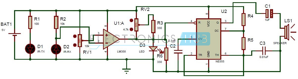
Super sensitive intrude alarm
This alarm uses IR sensor and infrared Led to detect the intruder. This uses 555 timer and comparator. When the intruder enters home, this circuit produces the sound using a speaker.

13 Responses
thank you guys for such a good ideas and infos !!!!
No doubt it is a inovative project. Thanks.
It’s a great
project!! Apprieciate more simple and efficient small projects!
what kind of resistors did you used?
Resistors used were 1/4 watt resistors
hy..i need cicuit design of burglar alarm uusing ic555.please some bady do share me whole description about it
thanks
I want detailed description about IC lm358 and function of each component in detail
I have question, is this same of Motion detector alarm
given circuit diagram is not correct
My led is not working but the connections arevas per the figure.
What may be the problem?
I am using burglar alarm output on not gate instead of probe but it is not working can you give the reason and solution of this problem
Hi,
I am doing this a project in schoola and was wondering is there anything missing from the circuit diagram and the breadboard
Do you have the pot set to a certain resistance and is there a certain distance required between the transmitter and reciever?
any help would be greatly appreciated.
Thanks
hey!!