In this simple DIY Project, I will show you how to design and implement a PIR Sensor based Security Alarm System. I have designed this circuit using Arduino as the main controller and of course the PIR Sensor itself. Additionally, I have used UM3561 IC, which is a Siren Generator IC, to produce the necessary Alarm sound through a Speaker.
Introduction
Generally, in security systems that are used in homes, shops, offices, etc., infrared or laser transmitters and receivers are used for accuracy and reliability. But these methods require a lot of monetary investment and infrastructure support.
A simple cost effective solution for Security Systems is implemented in this project where I will explain about a PIR based Security Alarm System, in which a PIR sensor is used instead of transmitter or receiver. This saves power consumption as well as it is a low cost implementation. PIR sensor is the short form of Passive Infrared Sensor.
PIR Sensor based Security Alarm Circuit Principle
The main idea of the circuit is to provide security. This is based on PIR sensor with an IC that produces siren. The PIR sensor detects the IR radiations emitted from the humans and it produces a digital output. This digital output is applied to the Arduino UNO.
Based on the digital signal from the PIR Sensor, Arduino UNO then triggers the UM 3561 siren IC. Thus it produces the sound when any human is detected.
The UM3561 is a ROM IC. It generates multi siren tones like ambulance siren, fire engine siren, police siren, machine gun sound.
PIR Sensor based Security Alarm Circuit Diagram
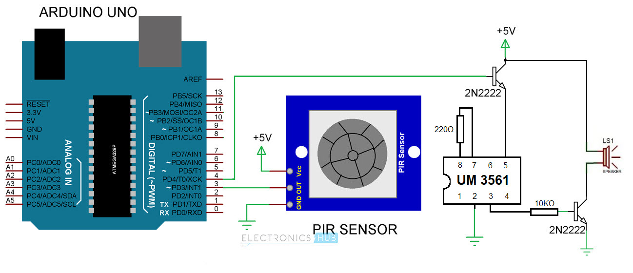
NOTE: The circuit diagram shows the Oscillator Resistor (between Pin 7 and 8 of UM 3561) as 220Ω but it is 220KΩ.
Circuit Components
- PIR sensor
- Arduino UNO
- UM3561 Siren IC
- NPN Transistor – 2N2222
- Resistors 10KΩ and 220KΩ
- Speaker 8Ω
- Breadboard
- Connecting Wires
PIR Sensor based Security Alarm Circuit Design
The designed system consists of Arduino UNO, PIR sensor, UM3561 IC, Speaker, transistor and a couple of resistors. The UM3516 IC is a Siren generator IC. It has 8 pins. First and sixth pins are the Sound effect selection Pins. Based on how they are connected, you can choose between 4 different types of sounds.
In this project, I have left open both the Pin 1 and Pin 6 to produce a Police Siren. Pin 5 is connected to +5V through an NPN Transistor (which is activated by Arduino UNO’s Pin 4).
One end of the 220KΩ resistor is connected to the seventh pin of the UM 3561 IC and the other end is connected to the eighth pin of the IC. Output is taken from the third pin of the IC and it is connected to a speaker through a resistor and transistor.
The base of the transistor is connected to the output of the IC through a resistor of 10KΩ. Emitter pin is connected to the ground while one end of the speaker is connected to the collector, while the other end is connected to +5V.
Coming to the PIR Sensor, its output is connected to Pin 3 of Arduino.
Code
Working of PIR Sensor based Security Alarm System
- Make the connections as per the circuit diagram and switch on the circuit.
- The PIR sensor is powered and it detects the IR rays emitted from any human.
- This PIR sensor has a range of 5 meters. You can adjust the pot provided for the sensor to vary this distance.
- When any human is detected, the PIR sensor outputs a logic HIGH value i.e. voltage of 3.5V to 5V to ARduino UNO’s Pin 3.
- As soon as the Arduino detects logic HIGH on Pin 3, it makes the Pin 4 HIGH for a duration of 10S. During this time, the Siren IC UM3561 is activated as its Pin 5 provided with +5V.
- The siren generator has an oscillator internally, to produce the sound.
- The oscillator circuit is tuned to a certain frequency and using a 220KΩ resistor externally.
- Then it is passed to the control circuit, which depends on tone selection pins.
- These tone selection pins decide one tone from different tones produced by the IC.
- Thus oscillations along with selected tone are sent to the address counter. The address counter then sends the data to the ROM.
- ROM then sends the tone on the output pin 3.
- The output is given to the NPN transistor to amplify the siren.
- The base of the transistor gets voltage from output pin of the siren generator.
- Transistor starts conducting when it gets the cutoff voltage at the base and the speaker is negative pin and is connected to the ground.
- Thus sound produced can be heard from the speaker when human is detected.
- In the present circuit, it produces Police Siren sound.
PIR Sensor Based Security Alarm System Applications
- This can be used in the museums to protect the valuable things.
- This can also be used as an automatic door bell circuit that rings the bell when human is detected.
- This can be used in defense applications to detect the humans in war field.
- This can be used in toy applications that produce sound.
Limitations of this Circuit
- PIR sensor pot should be adjusted in such a way to detect the humans only.
- This can detect the human only within its range of 5 meters.

20 Responses
The PIR Sensor based security systems are most reliable in your protection.
hi linda,
if you have any option please give me your project slide
thanks
shefat
The same effect can be achieved by using an ultrasonic distance sensor with Arduino connected to it and a buzzer or a speaker ???? right????
want more projects in my email address
How many seconds does it stay on when triggered? Can one select using like a variable resister to set the duration? Then it can be used to turn on and off lights in a room just by walking in and out.
This will be triggered until the PIR Sensor stops detecting..
How the pir can be adjusted to sense human beings
the transistor gets heated up while connected to suppy why??
WHY IT SAVES POWER CONSUMPTION?
I need that project report to help me Proceed with my Undergraduate degree research Thank u hope my request will meet Your positivity…
Hi,
Thanks for this simple project. When I connect the circuit except for Gnd connection, it always makes the sound.
IC pin 2, PIR pin 3 should it be connected to -ve 9v supply?
hello.can we use any other IC instead of UM3561?plz reply me fast..
you can use UTC 1618 or any other siren generating ICs
Which transistor should i use?
Here BC547(NPN) Transistor is used
Hy Anusha, Can I connect this with my Arduino Board? Coz m using it for Home security purpose. So the user should be able to switch off the circuit. So can u pls suggest me sumthng regarding tht?
Yes. Search for “GSM Based Home Security Alarm System Using Arduino”.
need more details about your project want to venture in it
Can 8 ohms speaker replaced by a buzzer
I deed power electrical how can someone lean this project ? What are procedures if you to this project ?