A Smoke Detector is a smoke sensing device that indicates fire. Smoke Detectors are very common in homes, offices, schools and industries. Smoke Detectors are very useful devices as the damage caused by fire accidents is catastrophic.
Now a days, smoke detectors and smoke alarms are very cheap as its usage is increasing and cost of manufacturing is decreasing. In this project, we are implementing a simple Smoke Detector Circuit using simple hardware.
We used a Gas/Smoke sensor for detecting smoke. The article is divided into information about Smoke sensor, circuit diagram and working.
A Brief Introduction to Smoke Sensor
There are two types of smoke detectors. Optical or Photoelectric smoke detectors and Ionization smoke detectors.
Optical smoke detectors consists of a light source like LED and a light detector like photocell.
The photocell conducts as long as the light falls on it. When there is smoke, the light from the source is interrupted and the photocell doesn’t conduct.
Ionization smoke detectors consists of two electrodes and an ionization chamber filled with ions. When there is no smoke, the ions move freely and the electrodes conduct normally.
In the presence of smoke, the chamber is filled with smoke and interrupts the movement of ions. The electrodes do not conduct anymore. Depending on the type of sensor and manufacturer, the conductivity conditions may change but the idea remains the same.
Based on the output of the smoke detector, an alarm system can be implemented.
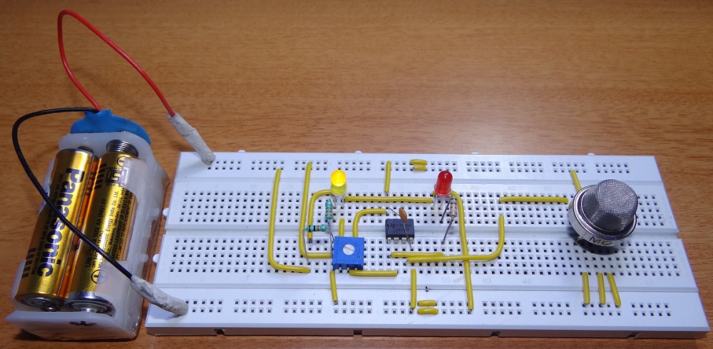
The sensor used in this project is MQ-2 Gas/Smoke sensor. It is sensitive to LPG, Hydrogen, Smoke, Methane, Propane, Alcohol, Butane and other industrial combustible gases.
It has two electrodes made of Aluminum Oxide (Al2O3) and a heating element made of Tin dioxide (SnO¬2) which acts as the main sensing layer.
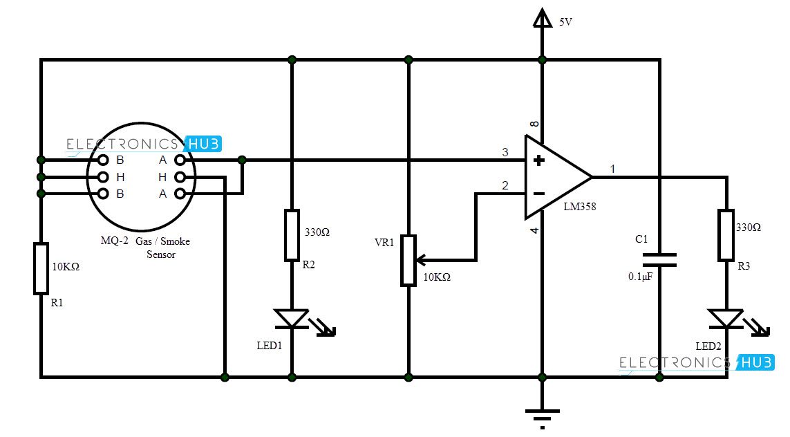
Circuit Diagram
Components Required
- MQ-2 Sensor
- LM358
- 10KΩ
- 330Ω
- LED
- 0.1µF
- 10KΩ POT
Working
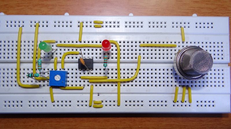
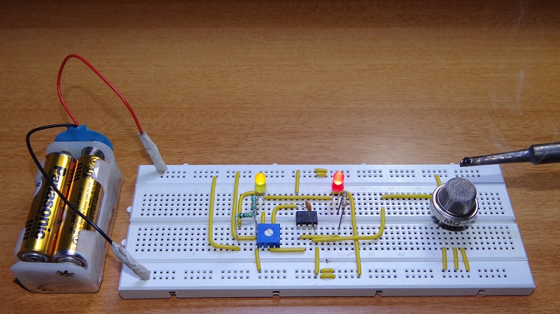
Smoke Detectors are amazing devices as they are small, cheap yet very useful. In this project, we implemented a simple Smoke Detector Circuit with adjustable sensitivity.
We used a Smoke Sensor MQ-2 as the main sensory device. The working of the circuit is simple and is explained below.
LM358 acts as a comparator in this circuit. The inverting terminal of LM358 is connected to POT so that the sensitivity of the circuit can be adjusted.
The output of LM358 is given to an LED as an indicator although a buzzer can be used as an alarm. The non-inverting terminal of LM358 is connected with output of smoke sensor.
Initially, when the air is clean, the conductivity between the electrodes is less, as the resistance is in the order of 50KΩ. The inverting terminal input of comparator is higher than the non-inverting terminal input. The indicator LED is OFF.
In the event of fire, when the sensor is filled with smoke, the resistance of the sensor falls to 5KΩ and the conductivity between the electrodes increases.
This provides a higher input at the non-inverting terminal of comparator than the inverting terminal and the output of comparator is high. The alarming LED is turned ON as an indication of presence of smoke.
Note
- The heating element in the Smoke Sensor must be preheated before it can sense any smoke or gas.
- The sensor gets hot because of the heating coil and it is advised not to touch the sensor while it is switched on.
- The sensitivity of the circuit to different concentrations of smoke can be adjusted by using the POT.
- The output LED can be replaced with a loud buzzer for effective alarm.

83 Responses
It is very essential project and very usefull to save valuable document kept in office and others.
its very good project to safe our environment
from what distance it can sense the smoke or what is its efficiency??
? Very Nice project ?
But Where is the ALARM?
An led is placed to indicate the smoke..So you can place a buzzer for sound
i want to know connections of sensor , cant you upload video?
you can replace the LED as ALARM(buzzer.).
it sense only smoke or gas or both gas and smoke
Its realy work
How to identify the noutch in the MQ-2 gas sensor????
There is no notch in the sensor. The terminals can be interchanged i.e. A and B can be interchanged in the circuit. Terminals marked “H” are heater coil ends. Even they can be interchanged.
Not working… Both LEDS are ON at normal air clean condition….plzz reply…the components required resistor values are different? Is it 330 ohm or any value?
The resistors are 330Ohms. They are used to limit the current flowing through the LEDs. You need to calibrate the sensitivity of the sensor with the help of potentiometer.
how to check if sensor is working ???
and approximately how much resistance is set in poteniometer when the circuit is working against 5 volts.
You need to calibrate the sensor beforehand using the potentiometer with some smoke around the sensor. The potentiometer must be adjusted according to the level of smoke you need to detect.
And how much resistace require for medium smoke.?
I don’t know how to calibrate please help me
But how to calibreate mq2 sensor?
may i know what is mean by the “preheat time” ?? is it means that i have to connect it to the circuit board for a certain amount of time so that the sensor might work ??
Yes. There will be a coil in the sensor, which must be heated (one end of the coil is connected to 5V and other end in connected to GND) for 30second to 1 minute before calibrating.
I have a MQ 2 sensor on a chip which has 4 terminals AO, DO, GND, VCC… Which terminal should be given as the input to the OpAmp… .. Reply to my mail plzz…. Email – parungowdamuldk@gmail.com
can we get the video of how to make..?
please can you send me a video of this project ?
Yes please…
Am about to try it prototype
how did it go?
thanks
guys why is it that there are 2 LED? are 2 of them has its own function or they both ON when a smoke detected? or the yellow one indicates that there is no smoke detected? Thank you!
The Yellow LED is a power ON indicator while the Red LED is used to indicate the smoke.
What ic is used??
Pls send a video of this project i am not getting properly
why do we need battery in the circuit? can we replace the output LED with a simple buzzer without any extra components for its connection? Can we also remove LED1 from the circuit?
Battery is used to show that the system is portable. A DC adapter can be used instead. The output LED can be replaced with a buzzer (It is better to drive the buzzer using a transistor). LED1 is s power on indicator. LED1 and R2 can be removed.
can this circuit be used for alcohol and lpg detection
Yess you can use but it may not give the accurate result..GO through Alcohol breathalyzer
what is the fullform of MQ2 & LM358
Can I use a 6V battery supply in this circuit?
yes you can use…
Plz upload the video related to dis project
wat is the battery voltage??and which transistor is to be used if i replace output led with speaker?
Plz tell me how to configure the sensor pins
I have a MQ 2 sensor which has 4 terminals AO, DO, GND, VCC… how can i connect with 4 terminals instead 6 terminals
Can anyone send the video of connection and working of this mini project through mail…?
shreyasnatraj97@gmail.com
is this equipment is avaliable in the mark ?..
if it available where should i try them..
is there any avalible in the online market?
plz reply…
How can I replace the output LED with an alarm? Do I have to change its connection or do I have to add any component? Thanks in advance 🙂
Small buzzers should work fine but it is suggested to drive the buzzer with a transistor.
thank u for updating this project
how do i wire the mq2? pls respond
MQ-2 has 6 pins. 3 on the left and 3 on the right. Pins on left and right can be interchanged (both top pins, both middle pins and both the bottom pins). Check the circuit diagram. We will upload the video.
hello sir, i am also student of entc dept nw i am working on that project please provide mi pcb layout of that project
Hi, We will upload the PCB files soon.
i did not find any MQ-2 sensor in my proteuios……….
anyone can help me……..plz
Hi, We do not have libraries for MQ-2 Sensors in Proteus. Try to build the project with physical components. It is very simple
Can i used 9v battery please reply
Yes. You can use a 9V battery.
sir,plz send me pcb layout dygram..ofsmoke detector..
can i use a 9v battery?
Yes. You can use a 9V battery.
sensor is not detecting properly. also the two LED both are function at the same time
You need to calibrate the sensor beforehand using the potentiometer with some smoke around the sensor. The potentiometer must be adjusted according to the level of smoke you need to detect.
thanks,i have tried to mount that circuit in the printed circuit board,but it is the best one,it runs very well.but the problem is that,i used level but for buzzer not running.can explain to me how to replace led by buzzer? thank
If you connected the buzzer directly, then drive the buzzer with a transistor and see. It should probably work.
can i replace the the MQ-2 with the ldr by using the same circuit ? As i know both of them are sensor and have the same function. And what is minimum input supply that i can i use?
Can I detect water vapor or steam?
How to connect mq2 sensor in breadboard ?
will u plz send me the video of dis project?
can I use mq6 behalf of mq 2
same circuit ..
hello
can i use MQ6 senosr instead of MQ2? thank you
please help me that what will happen if we increase or decrease the value of resistors ….
This is a great project. But how would I know if our sensor is working?
Do mq 2 sensor have polarity and what does that A H A and B H B means?
what is voltage of the analog out pin of the mq 2 gas sensor when it detect gas.
Pls can you upload the video of the circuit. and of the transistor should i use when replacing the LED with Buzzer
What is the work of capacitor and 10 k ohm resistance??can we work without them?
The 10KΩ Resistor is used to limit the current through the Sensor (just a safety measurement). The capacitor is a Bypass Capacitor (it dampens the AC elements and noise).
What type of smoke should I use to test the working of mq 2 gas sensor? Can incense smoke be used for it?
where can i get mq2 sensor for cheap online
Not sure about the price but you can find one in Amazon or ebay.
I’ve tried to build this circuit, but my Mq2 sensor heats when there is no smoke, the two LEDs are on, what could be the problem, please could you send me the video. thanks
Can we use mq 6 and lm 396
How I can connect MQ2 sensor on bread board . Please reply me!
This s a wonderful project work put can u send d the video through my email..Ederhifejidar@gmail.com
Can we use 9V battery
How can I connect the buzzer? I want to know the connection of buzzer, can you upload the circuit diagram for it?