In most of the measurement and instrumentation systems, test set-ups, electronic troubleshooting equipments and other electronic systems, signal generators are essential devices which are used to generate different waveforms (or signals) at specified frequency and amplitude.
These signals provided by the signal generators used to give an excitation to various electronic measuring devices and processing circuits in order to convert various transducer outputs into useful information.
The excitation from the signal generator can be stable AC or constant DC signals and also in some cases it is required to vary the amplitude as well as frequency of the excitation.
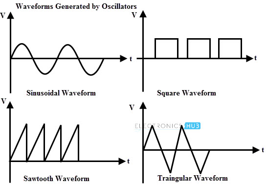
Some of the waveforms generated by the signal generators include sinusoidal, rectangular, triangular, square and pulse waveform. In some applications these waveforms are required to be at audio frequency as well as radio frequency.
Therefore, electronic circuits which generate such type of waveforms with certain magnitude and frequency are called as oscillators. There are different types of oscillators that can able to generate the output at high frequency up to gigahertz.
Before going to learn several types of oscillators, let us understand the basics involved in oscillator circuits.
What is Oscillator?
An electronic circuit used to generate the output signal with constant amplitude and constant desired frequency is called as an oscillator. It is also called as a waveform generator which incorporates both active and passive elements.
The primary function of an oscillator is to convert DC power into a periodic signal or AC signal at a very high frequency. An oscillator does not require any external input signal to produce sinusoidal or other repetitive waveforms of desired magnitude and frequency at the output and even without use of any mechanical moving parts.
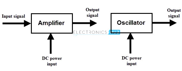
In case of amplifiers, the energy conversion starts as long as the input signal is present at the input, i.e., amplifier produces an output signal whose frequency or waveform is similar to the input signal but magnitude or power level is generally high. The output signal will be absent if there is no input signal at the input.
In contrast, to start or maintain the conversion process an oscillator does not require any input signal as shown figure. As long as the DC power is connected to the oscillator circuit, it keeps on producing an output signal with frequency decided by components in it.
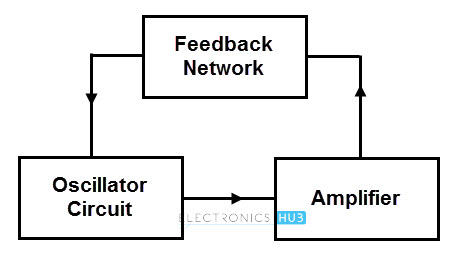
The above figure shows the block diagram of an oscillator. An oscillator circuit uses a vacuum tube or a transistor to generate an AC output.
The output oscillations are produced by the tank circuit components either as R and C or L and C. For continuously generating output without the requirement of any input from preceding stage, a feedback circuit is used.
From the above block diagram, oscillator circuit produces oscillations that are further amplified by the amplifier. A feedback network gets a portion of the amplifier output and feeds it the oscillator circuit in correct phase and magnitude.
Therefore, undamped electrical oscillations are produced , by continuously supplying losses that occur in the tank circuit.
Oscillators Theory
The main statement of the oscillator is that the oscillation is achieved through positive feedback which generates the output signal without input signal. Also, the voltage gain of the amplifier increases with the increase in the amount of positive feedback.
In order to understand this concept, let us consider a non-inverting amplifier with a voltage gain ‘A’ and a positive feedback network with feedback gain of β as shown in figure.
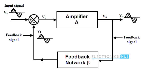
Let us assume that a sinusoidal input signal Vs is applied at the input. Since the amplifier is non-inverting, the output signal Vo is in phase with Vs. A feedback network feeds the part of Vo to the input and the amount Vo fed back depends on the feedback network gain β.
No phase shift is introduced by this feedback network and hence the feedback voltage or signal Vf is in phase with Vs. A feedback is said to be positive when the phase of the feedback signal is same as that of the input signal.
The open loop gain ‘A’ of the amplifier is the ratio of output voltage to the input voltage, i.e.,
A = Vo/Vi
By considering the effect of feedback, the ratio of net output voltage Vo and input supply Vs called as a closed loop gain Af (gain with feedback).
Af = Vo/Vs
Since the feedback is positive, the input to the amplifier is generated by adding Vf to the Vs,
Vi = Vs + Vf
Depends on the feedback gain β, the value of the feedback voltage is varied, i.e.,
Vf = β Vo
Substituting in the above equation,
Vi = Vs + β Vo
Vs = Vi – β Vo
Then the gain becomes
Af = Vo/ (Vi – β Vo)
By dividing both numerator and denominator by Vi, we get
Af = (Vo / Vi)/ (1 – β) (Vo / Vi)
Af = A/ (1- A β) since A = Vo/Vi
Where Aβ is the loop gain and if Aβ = 1, then Af becomes infinity. From the above expression, it is clear that even without external input (Vs = 0), the circuit can generate the output just by feeding a part of the output as its own input.
And also closed loop gain increases with increase in amount of positive feedback gain. The oscillation rate or frequency depends on amplifier or feedback network or both.
Barkhausen Criterion or Conditions for Oscillation
The circuit will oscillate when two conditions, called as Barkhausen’s criteria are met. These two conditions are
1. The loop gain must be unity or greater
2. The feedback signal feeding back at the input must be phase shifted by 360 degrees (which is same as zero degrees). In most of the circuits, an inverting amplifier is used to produce 180 degrees phase shift and additional 180 degrees phase shift is provided by the feedback network.
At only one particular frequency, a tuned inductor-capacitor (LC circuit) circuit provides this 180 degrees phase shift.
Let us know how these conditions can be achieved.
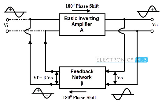
Consider the same circuit which we have taken in oscillator theory. The amplifier is a basic inverting amplifier and it produces a phase shift of 180 degrees between input and output.
The input to be applied to the amplifier is derived from the output Vo by the feedback network. Since the output is out of phase with Vi.
So the feedback network must ensure a phase shift of 180 degrees while feeding the output to the input. This is nothing but ensuring positive feedback.
Let us consider that a fictitious voltage, Vi is applied at the input of amplifier, then
Vo = A Vi
The amount of feedback voltage is decided by the feedback network gain, then
Vf = – β Vo
This negative sign indicates 180 degrees phase shift.
Substituting Vo in above equation, we get
Vf = – A β Vi
In oscillator, the feedback output must drive the amplifier, hence Vf must act as Vi. For achieving this term – A β in the above expression should be 1, i.e.,
Vf = Vs when – A β = 1.
This condition is called as Barkhausen criterion for oscillation.
Therefore, A β = -1 + j0. This means that the magnitude of A β (modulus of A β) is equal to 1. In addition to the magnitude, the phase of the Vs must be same as Vi. In order to perform this, feedback network should introduce a phase shift of 180 degrees in addition to phase shift (180 degrees) introduced by the amplifier.
So the total phase shift around the loop is 360 degrees. Thus, under these conditions the oscillator can oscillate or produce the waveform without applying any input (that’s why we have considered as fictitious voltage).
It is important to know that how the oscillator starts to oscillate even without input signal in practice? The oscillator starts generating oscillations by amplifying the noise voltage which is always present. This noise voltage is result of the movement of free electrons under the influence of room temperature.
This noise voltage is not exactly in sinusoidal due to saturation conditions of practical circuit. However, this nose signal will be sinusoidal when A β value is close to one.
In practice modulus of A β is made greater than 1 initially, to amplify the small noise voltage. Later the circuit itself adjust to get modulus of A β is equal to one and with a phase shift of 360 degrees.
Nature of Oscillations
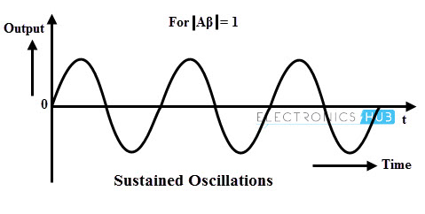
Sustained Oscillations
Sustained oscillations are nothing but oscillations which oscillate with constant amplitude and frequency. Based on the Barkhausen criterion sustained oscillations are produced when the magnitude of loop gain or modulus of A β is equal to one and total phase shift around the loop is 0 degrees or 360 ensuring positive feedback.
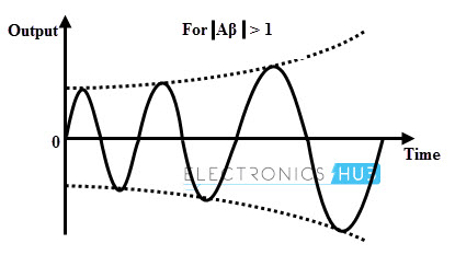
Growing Type of Oscillations
If modulus of A β or the magnitude of loop gain is greater than unity and total phase shift around the loop is 0 or 360 degrees, then the oscillations produced by the oscillator are of growing type. The below figure shows the oscillator output with increasing amplitude of oscillations.
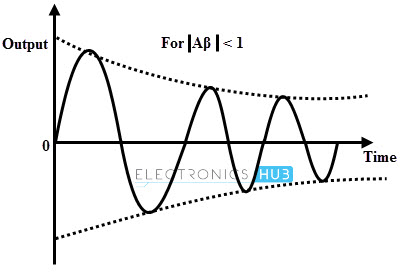
Exponentially Decaying Oscillations: If modulus of A β or the magnitude of loop gain is less than unity and total phase shift around the loop is 0 or 360 degrees, then the amplitude of the oscillations decreases exponentially and finally these oscillations will cease.
Classification of oscillators
The oscillators are classified into several types based on various factors like nature of waveform, range of frequency, the parameters used, etc. The following is a broad classification of oscillators.
According to the Waveform Generated
Based on the output waveform, oscillators are classified as sinusoidal oscillators and non-sinusoidal oscillators.
Sinusoidal Oscillators
This type of oscillator generates sinusoidal current or voltages.
Non-sinusoidal Oscillators
This type of oscillators generates output, which has triangular, square, rectangle, saw tooth waveform or is of pulse shape.
According to the Circuit Components
Depends on the usage of components in the circuit, oscillators are classified into LC, RC and crystal oscillators. The oscillator using inductor and capacitor components is called as LC oscillator while the oscillator using resistance and capacitor components is called as RC oscillators. Also, crystal is used in some oscillators which are called as crystal oscillators.
According to the Frequency Generated
Oscillators can be used to produce the waveforms at frequencies ranging from low to very high levels. Low frequency or audio frequency oscillators are used to generate the oscillations at a range of 20 Hz to 100-200 KHz which is an audio frequency range.
High frequency or radio frequency oscillators are used at the frequencies more than 200-300 KHz up to gigahertz. LC oscillators are used at high frequency range, whereas RC oscillators are used at low frequency range.
Based on the Usage of Feedback
The oscillators consisting of feedback network to satisfy the required conditions of the oscillations are called as feedback oscillators. Whereas the oscillators with absence of feedback network are called as non-feedback type of oscillators.
The UJT relaxation oscillator is the example of non-feedback oscillator which uses a negative resistance region of the characteristics of the device.
Some of the sinusoidal oscillators under above categories are
- Tuned-circuits or LC feedback oscillators such as Hartley, Colpitts and Clapp etc.
- RC phase-shift oscillators such as Wein-bridge oscillator.
- Negative-resistance oscillators such as tunnel diode oscillator.
- Crystal oscillators such as Pierce oscillator.
- Heterodyne or beat-frequency oscillator (BFO).
Frequency Stability of Oscillators
In oscillators, the frequency of oscillations remains constant over a long interval of time. Frequency stability is a measure of the degree to which the desired frequency is achieved. The closure will be the output to a constant frequency if the frequency stability is better.
The oscillation frequency depends on various features of the circuit such as various components, supply voltages, stray elements, characteristic parameters of active devices, etc.
Frequency instability or variations of the desired output frequency may be caused by variations in the external circuit elements or by device characteristics. In transistor oscillators such as a Hartley oscillator or Colpitts oscillators, the frequency of oscillations is not stable during long time operation.
This is because the capacitance existing at the base-collector junction in reverse biased condition is dominated at high frequencies and hence it affects the capacitor in tank circuit.
Also, due to change in temperature, the values of frequency dominating components like transistor, inductor, resistor, and capacitor also changes.
The variation of the frequency with temperature is given by
S wo T = (Δw / wr) (ΔT / Tr)
Where wr and Tr are the desired frequency and the operating temperature respectively. Δw and ΔT are change in frequency and change in temperature respectively.
The frequency stability can be given as
Sw = dθ/dw
A small frequency change in a desired frequency introduces the phase shift which is indicated as dθ. Hence the oscillator will be more stable if the circuit gives a larger value of dθ/dw.
The frequency stability can be improved by enclosing the oscillator circuit in a constant temperature chamber and by using zener diodes in the circuit to maintain the constant voltage.
A loading effect is reduced by coupling the oscillator circuit to the load loosely, or with the use of a circuit having a low output impedance and a high input impedance.
Amplitude Stability of Oscillators
The amplitude stability measures the amount by which the actual output amplitude varies from desired output amplitude in an oscillator. With the increase in the gain of the amplifier, the amplitude of the waveform is change.
The gain value is also changes due to the oscillator circuit components, and hence the amplitude. To keep the gain constant, various gain control techniques are used so that amplitude stability is maintained.
Another factor for variation of the amplitude is the supply voltage. The amplitude of the waveform changes with change in the supply voltage. For maintain the good amplitude stability, voltage regulators are used.
Factors Affecting the Stability of Oscillator
The stability of the oscillator includes both amplitude and frequency stabilities which depends on various factors. By considering the above discussed points in the listed form, we get following factors.
Operating Point
In case of transistorized oscillators, the changes in the device or transistor parameters (which are varied depends on the operation on non-linear portion) affect the stability of oscillator. Since the transistor is selected in such way that it operate in linear region of its characteristics.
Circuit Components
The values of circuit components like inductor, capacitor, and resistors are depend on the temperature. If the values of these components varied, there will be drift in the frequency of oscillations.
Inter-Element Capacitances
A transistor consists of inter element capacitance, i.e., the collector to emitter capacitor. If the value of this capacitor changes the oscillations frequency is also changing, hence the stability of the oscillator. This effect can be neutralized by placing swamping capacitor across the offending elements.
Power Supply
The variation in the DC supply voltage affects the oscillator frequency. This can be avoided by using regulated power supply.
Output Load
The Q-factor of the tank circuit depends on the output load and hence any change in load causes the change in frequency of the oscillation. For tuned oscillators, the frequency stability is proportional to the Q of a tuned circuit.

3 Responses
very useful my undergraduate course……… thanks a lot
Very very helpful. Easy to understand
Hi
thanks its very useful.
i have question:
how can i calculate amplitude of output in oscillator?