A Colpitts oscillator consists of two capacitive reactances and one inductive reactance in the tank circuit or feedback network. The circuit of Colpitts oscillator is similar to that of Hartley oscillator except the difference that rather than making tapped connection at the inductor junctions, it is made at the capacitor junction.
Hence the tank circuit forms a phase inverting network. Colpitts are used in applications which require generation of high frequency sinusoidal oscillations. These are commonly used in commercial signal generators up to 100 MHz.
Before discussing about circuit configuration of a Colpitts oscillator, let us know about the working of its tank circuit.
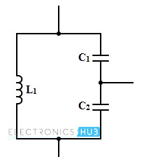
Colpitts Oscillator Tank Circuit
This sine wave oscillator tank circuit composed of a single inductor and two series connected capacitors that are grounded at their common connection as shown in figure. The C1 and C2 values are selected such that their ratio of the values produces the desired proportionate feedback signal.
Due to the series arrangement of these capacitors, the ratio of voltage across this arrangement is inversely proportional to their ratio values. Hence the total capacitance of the tank circuit is found by the product over sum rule as applied to the values of the capacitors.
Similar to the Hartley oscillator, the Colpitts oscillator consists of two major sections namely amplifier section and tank section. Each section is responsible for producing 180 degrees phase shift of the AC output voltage so the waveform at the output of this oscillator is like a standard sine wave when the time it leaves from the oscillator.
When the power supply is given to the circuit, transistor is turned ON by the small noise voltage as a biasing voltage. This causes the collector current to grow up thereby the capacitors C1 and C2 starts charging.
Once these are fully charged, they start discharging through the inductor L by settling up damped oscillations in the tank circuit.
Therefore, an AC voltage is developed across the combination of capacitors. The oscillations across the capacitor C2 are applied to the transistor at base-emitter junction.
These oscillations are amplified and phase shifted in the transistor amplifier. Thus, at the amplifier output, sustained undamped oscillations are produced.
The frequency of oscillations in the Colpitts oscillator is given by
f = 1/ (2π√ (LCeq))
Where Ceq = C1 C2 / (C1 + C2)
From the above equation we can observe that the Colpitts oscillator is similar to the other LC oscillators except the tank circuit. Usually these oscillators are tuned by varying inductance or capacitance of the circuit.
However, it is difficult to get a smooth variation using inductance L, so the capacitances C1 and C2 must be tuned simultaneously in the ratio of 100: 1 to get the variable frequency.
This is a difficult task which requires a special large value of variable capacitor. Therefore, for generating fixed frequencies of signals these oscillators are employed in general.
Example of a Transistorized Colpitts Oscillator
Calculate the frequency of oscillations of a Colpitts oscillator using a transistor having C1 = C2 = 0.001µF and L = 5µH. Also determine the value of the inductance if the operating frequency is doubled.
We know that, for a Colpitts oscillator the operating frequency is equal to the feedback network resonant frequency, i.e.,
f = 1/ (2π√ (LCeq))
Where Ceq = C1 C2 / (C1 + C2)
But in given data, C1= C2 = 0.001µF
Therefore, Ceq = (0.001× 10-6 × 0.001× 10-6) / (C0.001× 10-6 + 0.001× 10⁻⁶)
= 5 × 10⁻¹⁰ F
f = 1/ (2π√ (5 × 10-6 × 5 × 10-10))
= 3. 183 MHz
The new value of frequency, f = 2 × 3. 183
= 6.366 MHz
Therefore the operating frequency equation becomes
6.366 × 106 = 1/ (2π√ (L × 5 × 10⁻¹⁰))
L = 1.25 µH
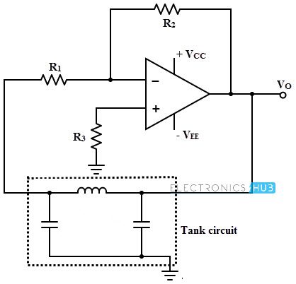
Colpitts Oscillator using Op-amp
In this type of circuit the op-amp is used in amplifier stage instead of transistor. The tank circuit remains the same as above discussed circuit. Thus the op-amp provides the basic amplification needed while the feedback network is responsible for setting the oscillator frequency.
The figure below shows the circuit diagram of Colpitts oscillator using op-amp. In the given circuit the op-amp is connected as an inverting amplifier with a high gain as compared with transistor circuit. The LC network is placed in a positive feedback of the operational amplifier
When the power supply is given to the circuit, there is no signal, but the small noise voltages are amplified by the op-amp. This makes the both capacitor to starts charging and discharging.
The part of the signal across the capacitor C2 is fed to the inverting amplifier. It is then amplified and keeps the network oscillating strongly. The oscillating frequency of the Colpitts oscillator using op-amp is given by
f = 1/ (2π√ (LCeq))
Where Ceq = C1 C2 / (C1 + C2)
Applications of Colpitts oscillator
- Colpitts oscillators are used for high frequency range and high frequency stability
- A surface acoustical wave (SAW) resonator
- Microwave applications
- Mobile and communication systems
- These are used in chaotic circuits which are capable to generate oscillations from audio frequency range to the optical band. These application areas include broadband communications, spectrum spreading, signal masking, etc.

2 Responses
Hi what are the industrial applications of Colpitt and Hartly
Can you explain the PNM Regulator?