LC oscillators are widely used to generate high frequency waves, hence these are also called as RF oscillators. It is possible to produce the frequencies at higher range (above 500 MHz) with the practical values of inductors and capacitors.
These types of oscillators are used in RF generators, high-frequency heating, radio and TV receivers, etc. These oscillators use a tank circuit consisting of inductor L and capacitor C elements. Before discussing about the LC oscillator circuit and its working, let us discuss about the basic operation of LC tank circuit.
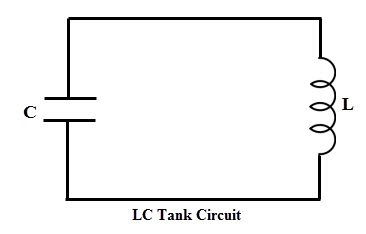
LC Tank Circuit
A tank or oscillatory circuit is a parallel form of inductor and capacitor elements which produces the electrical oscillations of any desired frequency. Both these elements are capable of storing energy. Whenever the potential difference exists across a capacitor plates, it stores energy in its electric field.
Similarly, whenever current flows thorough an inductor, energy is stored in its magnetic field. The below figure shows a tank circuit in which inductor L and capacitor C are connected in parallel.
Working of LC Tank Circuit
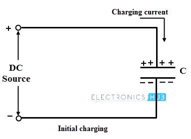
Let us understand the concept of electrical oscillations produced by this circuit. Consider that the capacitor is initially charged with a DC source having the polarities upper plate positive and lower plate negative as shown below.
This represents that the upper plate has of electrons deficiency , whereas the lower plate has excess of electrons. Therefore, potential differences exist between these two plates.
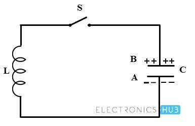
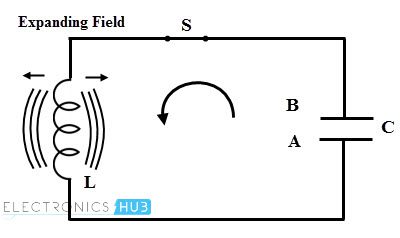
- Consider that this charged capacitor is connected across the inductor through a switch S as shown in figure. When the switch S is closed, the conventional current flow or electrons moves from plate A to B through the inductor coil. Therefore the energy stored or strength of the electric field in the capacitor decreases.
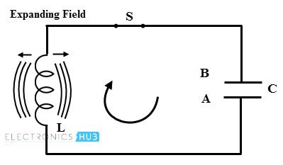
- The current flowing through the inductor induces an EMF which opposes the electrons flow through it. This current flow set up a magnetic field around the inductor thereby it starts storing the magnetic energy. When the capacitor is fully discharged, current or electron flow through the coil becomes zero. At this time magnetic field has maximum value and there is no electric field.
- Once the capacitor is fully discharged, magnetic field around the inductor starts collapsing and produces the counter emf. As per the Lenz’s law, this counter emf produces the current which begin to charge the capacitor with opposite polarity by making plate upper plate negative and lower plate positive as shown in figure below.
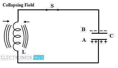
- When the capacitor is fully charged in opposite direction, the entire magnetic energy is converted back into the electric energy in capacitor, i.e., magnetic energy is collapsed. At this instant, capacitor starts discharging in the opposite direction as shown in figure. Once again the capacitor is fully discharged and this process will be continued.
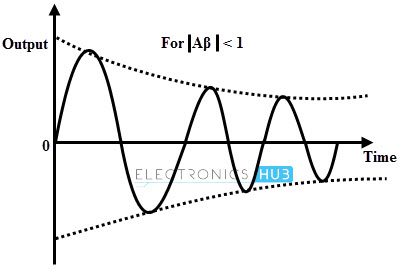
- This continuous charging and discharging process results an alternating motion of electrons which is nothing but an oscillating current. But these oscillations of the capacitor are damped because every time transferring of energy from L to C and C to L dissipates energy in the form of heat in the resistance of the coil and in the connecting wires in the form of electromagnetic radiation. These losses decrease the amplitude of oscillating current gradually till it ceases. These are called as exponentially decaying oscillations or damped oscillations.
Frequency of LC Oscillator
Concept of Resonance
If the circuit with capacitor, inductor and resistor is excited with constant voltage with time varying frequency, then the reactance of both inductor-resistor RL and capacitor-resistor RC are also varied. Thus the amplitude and frequency of the output are varied as compared with input signal.
The inductive reactance is directly proportional to the frequency whereas the capacitive reactance is inversely proportional to the frequency. Therefore, at lower frequencies, capacitive reactance of the inductor is very low and acts as short circuit whereas the capacitive reactance is high and acts as open circuit.
At higher frequencies, reverse will happen i.e., capacitive reactance acts as short circuit whereas inductive reactance acts as open circuit.
At a particular combination of capacitor and inductor, this circuit becomes resonant or tuned circuit that has a resonant frequency at which both inductive reactance and capacitive reactances are identical and cancel with each other.
Hence there will be only resistance is present in the circuit to oppose the flow of current and therefore there will be no phase shift current from the voltage by using a resonant circuit. The current is in phase with the voltage.
The sustained oscillations can be obtained by providing the supply energy to L and C components. Therefore, LC oscillators use this tank circuit to produce the oscillations.
The frequency of oscillations generated by this tank circuit entirely depends on the values of capacitor and inductor and their resonance condition. It can be expressed as
XL = 2π f L
XC = 1/ (2π f C)
At resonance, XL = XC
2π f L = 1/ (2π f C)
f2 = 1/ ((2π)2 L C)
f = 1/ (2π √ (LC))
Basic Form of LC Oscillator Circuit
In this oscillator, amplifier and LC filter network can be constructed in several ways. Thus, these oscillators are come in different forms such as Hartley oscillators, Armstrong oscillator, Colpitts oscillators, Clapp oscillators, etc. Before we discussing about all these oscillators in further articles, let us learn some basic working of LC oscillator circuit.
As mentioned above that a LC oscillator consists of an amplifier and tuned LC circuit as feedback network. For the LC oscillator circuit, amplifier stage can be built by using active devices like op-amp, bipolar junction transistor, or FET.
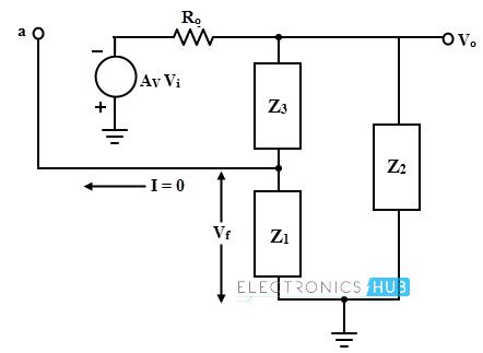
The basic form of the oscillator is shown below with amplifier gain A. The feedback network consists of impedances Z1, Z2 and Z3 which can be either capacitance or inductance. This feedback network is supplied with the output of amplifier.
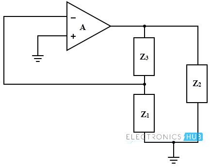
The amplifier circuit provides 180 degrees phase shift while additional phase shift of 180 degrees is provided by the feedback circuit to satisfy the condition of oscillations. Consider the equivalent circuit of the LC oscillator in which Ro is the output resistance of the amplifier and ZL is the load impedance connected at the output of amplifier.
The general gain expression of the amplifier for above circuit with load (AL) and without considering feedback is given by
AL = – A ZL / (Ro + ZL)
The negative sign indicates the 180 phase shift in the amplifier stage.
By considering the feedback, feedback network gain is given by
β = Z1 / (Z1 + Z3)
But this feedback network must introduce 180 digress phase shift and then
β = – Z1 / (Z1 + Z3)
To satisfy the Barkhausen condition of oscillations, – Aβ must be equal to 1, then
A β = – A ZL Z1 / (Ro + ZL) × (Z1 + Z3)
This is the required loop gain expression.
Now, The load impedance ZL = Z2 (Z1 + Z3) / (Z1 + Z2 + Z3)
Solving the loop gain expression with ZL then we get
A β = – A Z1 Z2 / (Ro (Z1 + Z2 + Z3) + Z2 (Z1 + Z3))
Substituting Z1 = j X1, Z2 = j X2 and Z3 = j X3
A β = A X1 X2 / (jRo (X1 + X2 + X3) – X2 (X1 + X3))
To produce the 180 phase shift by this feedback network, the imaginary part of the denominator must be zero, i.e.,
(X1 + X2 + X3) = 0 this implies that –X2 = X1 + X3
Then the equation becomes,
A β = A X1 / (X1 + X3)
A β = – A (X1 / X2)
But the Barkhausen condition is – Aβ = 1. Then
A (X1 / X2) = 1
This means X1 and X2 must be either inductive or capacitive (similar type of reactance) and the condition for oscillations is obtained as
A = (X2 / X1)
For Hartley oscillator both X2 and X1 are inductors whereas for Colpitts oscillators both are capacitors. And also –X3 = X1 + X2, thus X3 is capacitor in Hartley oscillator and is a inductor in Colpitts oscillator.
Example
Find out the value of inductor needed with a capacitor of 47 pF for a tuned LC oscillator frequency of 22.7 MHz.
The resonant frequency of the LC oscillator is
f2 = 1/ ((2π √ (LC))2
L = 1/ (4π2 f2 C)
L = 1/ (4π2 (22.7 × 10⁶)2 × 47 × 10-12)
L =1.04micro Henry
