Relaxation oscillators are widely used in applications with relaxed phase-noise requirements in a form of fully integrated circuits as they do not consists of inductors. In contrast to LC oscillators, relaxation oscillator consist only one energy storing element.
The oscillatory waveform depends on the nonlinear characteristics of the circuit rather than on a frequency selective element. Therefore, these are easy to fabricate as monolithic integrated circuits.
Relaxation Oscillator
Relaxation oscillators are non-sinusoidal oscillators which generate triangular, square and pulse waveforms using a circuit building block known as multivibrators. When the loop gain is greater than unity and the feedback is positive then the output produced is nearly similar to the sine wave which last for most of the periodic time.
In that state the amplifier is either in the state of saturation or cut off. These types of oscillators are called as relaxation oscillators.
In such oscillators, amplifiers used act as high-gain amplifier for short period of time and then wait for a change to takes place. Therefore, the frequency of oscillations does not directly depend on natural frequency of LC circuit or phase shift.
The time intervals at which the amplifier is not in the active part of the circuit decides the frequency of oscillation. Relaxation oscillator uses a device to change states and an RC timing circuit to generate a periodic output waveform.
During one phase of oscillation, a relaxation oscillator stores the energy in reactive element or component and in the next phase of the cycle it gradually releases the energy.
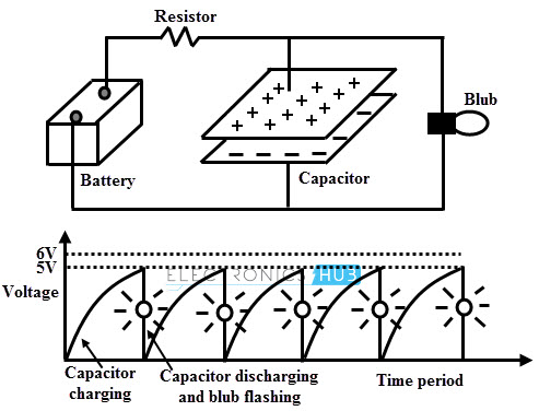
The relaxation oscillator concept is illustrated in the above figure in which a flash bulb is illuminated periodically for certain interval of time. The circuit arrangement consists of a battery, capacitor and bulb with 5V firing threshold.
When the capacitor is charged to the firing threshold level of the blubs, the capacitor starts discharging and supplies its stored energy to the blub.Then the bulb starts flashing for a time given by the time constant of the capacitor and resistor combination.
After the flash the capacitor again starts charging and this will be continued or repetitive. The repetitive time depends on the charging and discharging times. The same principle is applied in relaxation oscillator and hence it is a repetitive circuit.
Relaxation oscillators are divided into two classes namely sawtooth oscillators and astable multivibrators. In first case, conduction of switching device causes the capacitor to discharge rapidly and instantly so the total output waveform takes up by the charging period alone virtually.
In astable type both charging and discharging of the capacitor takes place slowly through a resistor. Hence the total output waveform contributed by these two periods.
UJT Relaxation Oscillator Circuit
The below figure illustrates the construction of relaxation oscillator using unijunction transistor (UJT). An RC combination circuit connected at the emitter terminal of the UJT determines the frequency of oscillations. Resistors R1 and R2 are employed as a current limiting resistances as shown in figure.
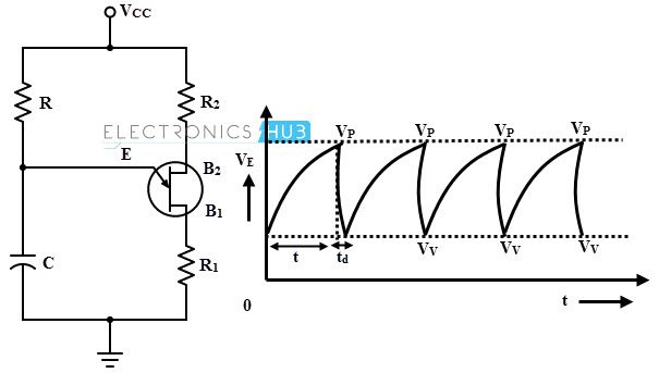
When the circuit is energized with DC voltage, UJT remains in OFF condition and the capacitor starts charging through the resistance R. Since the emitter terminal of the UJT is connected to the capacitor, the capacitor voltage considerably effects the performance of UJT. When the voltage across the capacitor becomes the peak voltage of the UJT, UJT is driven into conduction mode.
At this stage, the emitter–base1 resistance collapse and hence the capacitor starts discharging. When the voltage across the capacitor becomes the valley point voltage of the UJT, the emiiter-base1 resistance reverts back to the high resistance and hence the UJT drives into cutoff mode.
Therefore the capacitor again starts charging and this process is repeated and results a sawtooth waveform across the capacitor as shown in figure.
Astable Multivibrator Circuit
It is a relaxation oscillator which generates periodic square waves. The amplitude of the square wave is constant for some period of time and after which it changes abruptly to another level, further stays constant there and these abrupt changes go on periodically.
The below figure shows the astable multivinrator circuit in which continuously generates square wave without any external signal. It consists of two stage resistance coupled amplifiers and output of the each stage is coupled to each other as regeneration as shown in figure.
It consists of two quasi stable states and the associated circuit changes its state from one quasi state to the other without any triggering.
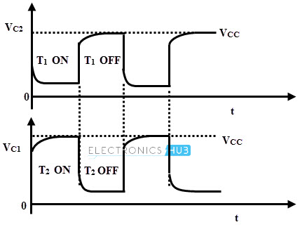
When the power supply is given to the circuit, T1 conducts more than T2 (due to the unsymmetrical components of the two stages circuit get imbalanced) that means the collector current of T1 is more than that of T2 and hence Vc1 is less than Vc2.
Since this voltage Vc1 is coupled to the base of T2, the collector current of T2 further reduces and finally Vc2 approaches to Vcc. This process will be continued till the transistor T1 is fully ON and T2 is fully OFF. This is the one quasi-stable state during which C2 charges through Rc2.
Meanwhile the capacitor C1 (which was already charged) discharges through T1 and R1making base of the T2 suddenly Vcc. Therefore, no current flows through the base of T1 and it stops conducting. Now, T2 starts conducting as the base current to it increases.
This process will be continued till T2 is fully ON and T1 is fully OFF. This is another quasi stable state. The voltages Vc1 and Vc2 take square wave shape which are complementary to each other while this entire process continues.
Relaxation Oscillator Circuit using Opamp
The figure below shows an operational amplifier version of relaxation oscillator in which the output switches back and forth between the two saturation limits of the op-amp. The output is taken at the operational amplifier output and this output charges the capacitor through the resistor R.
When the power supply is given to the circuit, the capacitor starts charging towards Vcc through the resistor R. Whenever the voltage across the capacitor reaches to the trigger voltage of the op-amp, the op-amp switches and the output voltage reverses to its opposite saturation limit.
Then the current through the resistor changes sign and the capacitor starts relaxing towards opposite threshold. The trigger threshold voltage at the op-amp’s positive input also changed so that when the capacitor voltage reaches to this threshold, the op-amp output again changes its state.
This process will be repeated. Typical waveforms of the op-amp output voltage and voltage across the capacitor are shown in figure.
Relaxation Oscillator Circuit using 555 Timer
A relaxation oscillator or astable multivibrator can be implemented by using 555 timer and its circuit is given below. The pulse width of the output waveform depends on the RC time constant. The circuit is connected as, Pin 4 is connected directly to the supply; Pin 6 and Pin 2 are shorted together; and at Pin 3 output is taken out.
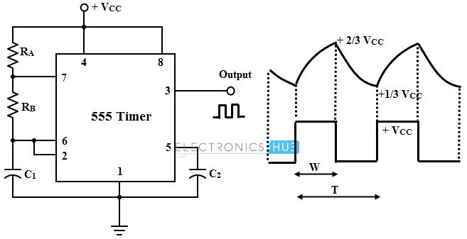
When the supply voltage is given to the circuit, the capacitor starts charging using the power supply Vcc. Then the output is high at pin 3 (due to the open discharge terminal).
When the capacitor voltage reaches to 2/3 Vcc, the internal flip flop changes and the discharge terminal is shorted to the ground, hence the output goes low. The operating frequency can be altered by varying the values of resistor and capacitor.
By operating the 555 timer in this way, it has no stable states, which merely means that it cannot remain indefinitely in either state. Therefore a series of rectangular pulses are obtained at the output terminal.
Applications of Relaxation Oscillators
These oscillators are used in many applications and some of those are listed below.
- Oscilloscopes
- Television receivers
- Stroboscopes
- Electronic camera flashes
- To generate clock signals in digital circuits
- Used for firing the thyristor based circuits and equipments

One Response
Thanks for the concept