In this article, we will see different LED Running Lights Circuits, which are also called as LED Knight Rider Circuit. These circuits can be employed on a car, motor cycle, bike etc. as they will present an eye catching look to the viewers.
We have created 4 different LED Running Lights Circuits using very simple components. In the first circuit, we have implemented a Flashing LEDs with the help of transistor based Astable Multivibrator.
The second circuit is based on IC CD4017, where we have Chasing LEDs. In this, the LEDs simply turn on one after the other in a sequential fashion. The third circuit is also implemented using CD4017. In this circuit, the LEDs will glow in a different pattern i.e. two way running LEDs.
In the final circuit, the LED initially travel in the one way and then travel in reverse direction. It means, the pattern is same as a pendulum as it travels back and forth.
This circuit can be utilized for the beautification of the car or it can be helpful at the time of crisis when your car broke down and you need help.
We will see the details of each of these circuits like circuit diagram, components required and working in the following sections.
Related Post: LED Christmas Lights Circuit
Outline
ToggleSimple LED Running Light Circuit (Flashing LEDs)
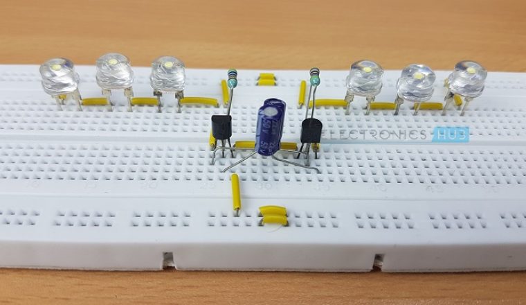
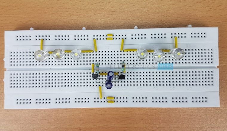
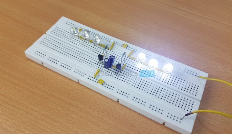
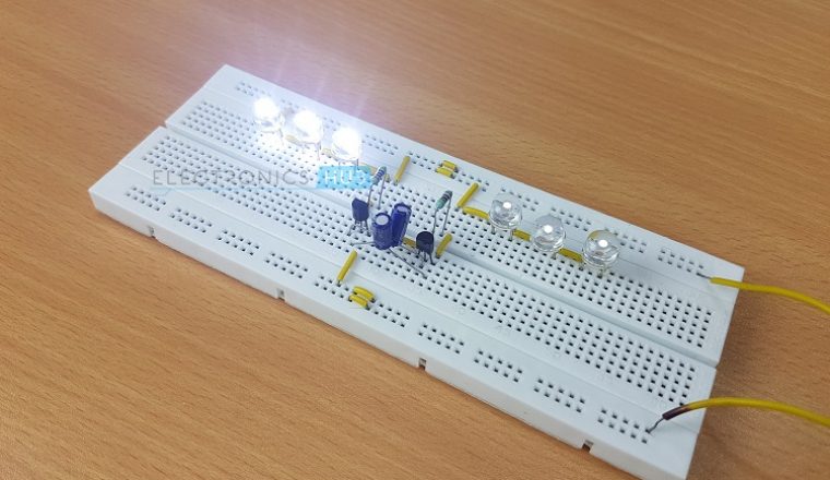
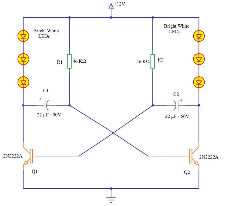
In this project, we have designed a simple Flashing LED Circuit. We have used two sets of LEDs (3 on one side and 3 on the other) that will be turned on alternatively so that the outcome is a bright flashing LEDs.
Circuit Diagram
Components Required
- 2 x 2N2222A (NPN Transistor)
- 2 x 22µF – 50V Capacitor (Polarised)
- 2 x 46 KΩ Resistor (1/4 Watt)
- 6 x 8mm Bright White LED
- 12V Power Supply
- Connecting Wires
- Breadboard
Working of the Project
From the circuit diagram, it is clear that the project is based on simple Astable or a Free Running Multivibrator. When switch on the circuit, one transistor will be ON (in Saturation) and the other will be OFF (Cutoff).
Assuming Q1 is ON and Q2 is OFF, the Capacitor C2 will charge through series LEDs. Since the LEDs are connected in the path of the current, they will light up.
During this time, the transistor Q2 is OFF because of the discharging capacitor C1 (as the negative plate is connected to the base of Q2). After the time constant C1R1, the capacitor C1 is completely discharged and starts charging through R1.
The charging direction is reverse. As the capacitor charges, it builds up sufficient voltage (0.7V) to turn ON the transistor Q2. At this time, the capacitor C2 starts discharging through Q2.
As the plate of the capacitor C2, which is connected to the base of the transistor Q1, becomes negative, the transistor Q1 is turned OFF and this set of LEDs are turned OFF.
Now, the capacitor C1 starts to charge from the corresponding series LEDs (through base of Q2). As this set of LEDs are connected in the current path, they will be turned ON.
Now the capacitor C2 discharges and after complete discharge, it will start charging through R2. As the charge builds up in the capacitor C2, when the voltage reaches 0.7V, it will turn ON the transistor Q1. From this point the process repeats as earlier.
LED Chaser Circuit using CD4017 and 555
The second project in the LED Knight Rider Series is an LED Chaser circuit using CD4017 Decade Counter and 555 Timer IC. We will see the circuit diagram, components used and the working of this project
Circuit Diagram
Components Required
- 1 x CD4017 Decade Counter IC
- 1 x 555 Timer IC
- 1 x 18 KΩ Resistor (1/4 Watt)
- 1 x 2.2 KΩ Resistor (1/4 Watt)
- 1 x 100 KΩ Potentiometer
- 1 x 1 µF – 50V Capacitor (Polarised)
- 1 x 0.1 nF Ceramic Disc Capacitor (100 pF code 101)
- 10 x 8mm Bright White LEDs
- Connecting Wires
- 5V Power Supply
- Breadboard
Working of the Project
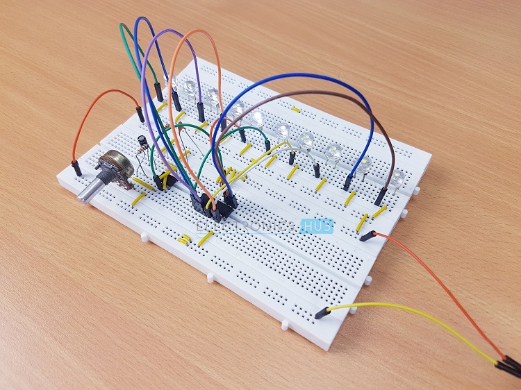
In this project, we have designed a simple LED Chaser Circuit, where the LEDs turn ON one after the other and give us the effect of one LED chasing the other. We will now see the working of this project.
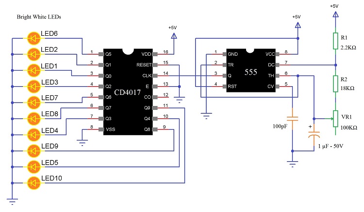
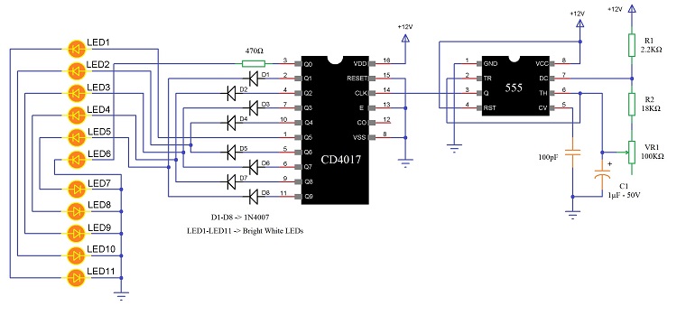
First thing we notice in the circuit diagram is that there are two parts in the circuit: the 555 Timer part and the CD4017 Decade Counter IC part with LEDs. The 555 Timer IC in this project is configured as an Astable Multivibrator.
In this mode, it generates a pulse whose frequency is determined by the components R1 (2.2 KΩ), R2 (18 KΩ), VR1 (100 KΩ) and C1 (1µF). The frequency of the pulse can be controlled by adjusting the 100 KΩ POT.
This pulse is given to the CD4017 Decade Counter IC as its clock input. By understanding the working of CD4017, for every clock pulse it receives at the Clock Input pin, the count in increased by 1 and as a result each output pin will be HIGH for every corresponding clock pulse.
As it is a decade counter, we will get a count of 10 and since we connected the bright white LEDs to the output pins, each LED will be turned ON when the corresponding pin becomes HIGH.
After 10 clock pulses, the count is reset and will start from the beginning. If the LEDs were placed in a circular fashion, we get the feel and look a Chasing LED effect.
Two Way Running LEDs with 11 LEDs, CD4017 and 555 Timer IC
This is another running LED circuit but the difference between this and the previous Running LEDs circuit and this circuit is that in the previous circuit, it was designed as a one way running LEDs circuit whereas in this circuit, the LEDs will be running in two ways.
Circuit Diagram
Components Required
- 1 x CD4017 Decade Counter IC
- 1 x 555 Timer IC
- 1 x 18 KΩ Resistor (1/4 Watt)
- 1 x 2.2 KΩ Resistor (1/4 Watt)
- 1 x 470 Ω Resistor (1/4 Watt)
- 1 x 100 KΩ Potentiometer
- 1 x 1 µF – 50V Capacitor (Polarised)
- 1 x 0.1 nF Ceramic Disc Capacitor (100 pF code 101)
- 8 x 1N4007 PN Junction Diodes
- 11 x 8mm Bright White LEDs
- Connecting Wires
- 12V Power Supply
- Breadboard
Working of the Project
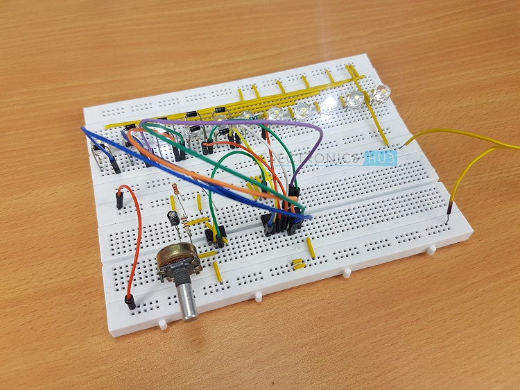
The working of the Two Way Running LEDs project is similar to that of the LED Chaser Circuit except that the orientation of the LEDs is different. We will see the working of this project now.
The 555 Timer part (the operation is similar to the one explained in the above circuit) generates a pulse signal, which is given to the CD4017 Counter as the clock input. The LED6, which is connected to the Q0 of the CD4017 will light up first.
The LED5 and LED7, which are connected to Q1 of CD4017, will light up next. The connections continue as shown in the circuit diagram and this process continues till Q5, which is connected to LED1 and LED11. Until this step, one way lighting of the LED will be completed.
In order to achieve the two way lighting up of the LED, Q6 is connected to LED2 and LED10, Q7 is connected to LED3 and LED9 and so on.
The final effect will be a Two Way Running LEDs and the sequence will be as follows: LED6 (Q0), LED5 – LED7 (Q1), LED4 – LED8 (Q2), LED3 – LED9 (Q3), LED2 – LED10 (Q4), LED1 – LED11(Q5) for one way and followed by LED2 – LED10 (Q6), LED3 – LED9 (Q7), LED4 – LED8 (Q8), LED5 – LED7 (Q9).
Circuit Diagram of LED Knight Rider Circuit Diagram:
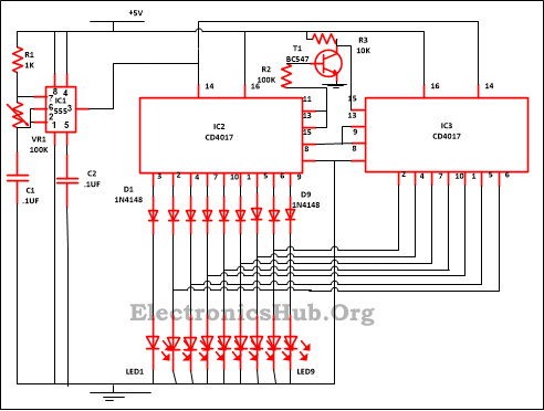
Components Required for the Circuit:
- IC
- NE555 – 1
- CD4017 – 2
- Resistor
- R1 (1K) – 1
- R2 (100K) – 1
- R3 (10K) – 1
- VR1 (100K) – 1
- C2, C1 (.1uf) – 2
- D1-D9 (1N4148) – 9
- Transistor (BC547) – 1
- LED1-LED9 – 9
Description:
In order to get familiar with the working layout of the circuit it is important to get familiar with individual pin.
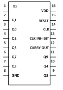
This IC has 16 pins out of which 3 are input pin, 10 is for output purpose and for ground one pin is assigned and one power supply and rest one left is for Carry out. As shown below pin diagram of IC CD4017.
- Reset Pin (Pin 15) – The counter is reset to zero by this pin. Suppose you wish that the counter starts counting from the third pin then you need to attached fourth output with 15 pin. So after each third output the counting automatically begins with zero.
- Clock Pin (Pin 14) – The output will be provided each time the pin 14 of the IC move to high. Like for the initial pulse of the clock pin 3 will give you output likewise for the next clock pulse arrive the output will be provided by pin2 and so on. After 10 clock pulse it will once more begins from Q0 output.
- Clock Inhibit Pin (Pin 13) – This pin is used to change the state of the counter from ON to OFF and vice versa. Pin 13 should reach the highest state if you wish to switch off the counter. If it is at high state then it will not pay attention on the clock pulse no issues that you press the switch how many of times, implies that the count will not go forward. Pin 13 in our circuit is grounded.
2. Output Pin (Pin Q0 – Q9) – In the sequential manner the output is received from these pins. Like pin 3 will give you output for the first pulse and so on.
3. Ground Pin (Pin 8) and Supply Pin (Pin 16) – For the working of the IC pin 8 provide ground while power supply is provided by pin16.
4. Carryout Pin (Pin 12) – With the help of this pin one or more than one IC CD4017 can be linked. Suppose you desire to attach one more CD4017 then attach pin 12 with input clock of its descendant. The carry pin of primary CD4017 is coupled with the second clock input similarly the second carry pin is coupled with the third clock input and so on. You can see this in circuit diagram.
NE555 and CD4017 are the two IC on which the circuit is based along with some other components. In this circuit IC 555 timer is used like an astable oscillator.
IC CD4017 is used as a CMOS counter/driver. Every time when it gets to clock pulse , it fetches the clock pulse through clock input and all 10 outputs turn on in sequence. It is well known IC and it is very much useful in various other projects viz Light Chaser, Matrix Die.
IC NE555 in this circuit is used as an astable mode , used to produce a clock pulse for the circuit. This is used to give an oscillating wave to pin 3 of the IC1 which is for output.
By the help of VR1 the speed of oscillation can be alter. 555 timer oscillation frequency can be calculated by-
f=1. 44/(R1+2* (VR1) *C1)
In this circuit, the counting will start from 0 till 16 since we have employed two decade counters. IC2 in the circuit done the counting 0 to 9 while with the help of diodes the rest of the counting will done by IC3.
In the instance when 555 timer gets the power supply, pin 3 of IC1 output is given to CD4017 pin 14 of decade count, which in turn give clock pulse for the IC2 working. CD4017 begins its counter value from zero (since it has inbuilt counter) after getting the clock input.
And after pin 14 moves to high it forwarded one by one to every pin. Like at the primary stage output Q0 will receive at pin 3 and LED1 will blink and LED2 will glow from pin4 and so on.
When the counter arrives at the pin 11 i.e ninth output it will create it temporary high, which is coupled to pin 13 (clock inhibit). The clock pulse will be disregarded from pin 14 if the pin is at high and the counting stop by IC2.
And in return of these IC3 pin 15 became low because earlier transistor BC547 is a high state. And pin15 of IC3 reset to low state due to this low signal for a short moment and the output of IC3 stats counter from Q0 (pin3) and move forward one by one.
When it arrives at Q8 which is pin 9 which is yet again connected with pin13 of IC3 due to stop counting of IC3 irrespective of the input signal. Pin 14 disregard the clock pulse if pin13 is at high which implies IC3 stop counting.
And this will once more given to reset pin 15 of IC2 and counting is now begin by IC2, counting of IC3 disabled.
It also means that when the output counting is done by IC2 from IC3 is stop similarly IC2 stop when IC3 counts. Hence output signals approaching from IC3 are transmitted in reverse direction to IC2.


12 Responses
i want 555 timer project
thnk you !
I cant get it to work any one else having trouble?
HE HAS THE leds IN BACKWARDS ON THE SCHEMATIC. JUST TURN EACH LED AROUND RESPECTIVLY AND IT WILL BE FINE
When i connect 12v the only result i get is LED 2,3,4,5,6,7,8,9,10 are lit solid. No flash, no sequential , i have checked and rechecked my wires everything is correct. Only difference is my 4017 IC is 4017BD and i donot have 8MM white high brightness LEDS. I have used 1-10MM high brite white,
7-10MM high brite RED, 2-10MM BLUE HIGH brite, and 1 – 5 MM WHITE. Very frustrated as I have NOT been able to make ANY sequential circuit work yet! Possible i have bad 555? Wrong 4017??? How do i test these components? I have swapped them out for others but no success!!Any help would be great. Im about to trash my “lab”! And give up on this hobby! ANYONE PLEASE HELP
I think you had better go back and read the CCT Diag.
It does say 5V DC working!
Sory, one CCT Diag does say 12V but you must not put 12V DC up either if these chips!
It’s awesome … My first project … I’m new and without the knowledge of resistor and stuffs I… made one way chaser using CD4017 and 555 (used 22k resistor instead 18k) … Worked well
And now could you please help me to reverse the chase in another way ? I’m making indicator light for my bike and want to make for both side …
hi is this a monostable or astable circuit or is it neither of it?
Astable!!!
how about running with 100 LED in one row ?
and spread onto 20 colomns,
100 x 20 LED ?
I want a curcuit having two parllal line led light