In this project, I will show you how to design a simple Bike Turning Signal Circuit using 555 Timer IC, couple of LEDs and a few other easily available components.
Introduction
Turn Indicator Lights also known as Directional Indicators (formally) or Blinkers, Flashers (informally), are an essential part all automobiles whether a bike or a car. They inform other road users our intent to turn left or right. There are several regulations and standards that manufacturers must comply with while designing and integrating Turn Lights on to a vehicle.
Bike Turning Signals are used to indicate the intent of left turn or right turn to other users of the road. Have you ever tried to design bike turning indicators? This article explains you how to design these bike turning indicators.
Bike Turning Signal Circuit Principle
The objective of this circuit is to indicate left or right turn for bike/vehicle. The main component of this circuit is the infamous 555 Timer IC. Here, this 555 timer acts as an Astable multi vibrator. It generates the pulse signal with variable width. Using this variable width of the pulse, we can set different time delays for the LEDs (ON and OFF for LEDs).
The circuit consists of two important resistors (100KΩ and 470KΩ), which are connected to 555 timer and these are used to set the time delay for LEDs. The output of the 555 Timer IC is given to either LEFT indicator LED or the RIGHT Indicator LED using a Slide Switch.
1n4148 signal diode is connected in reverse bias at the output to maintain constant current at the output. BC547 (NPN) Transistor switches the LED’s ON and OFF based on the base currents. 330 ohm resistors are used to drop the voltage otherwise LEDs may get damaged. Here we can vary the time width of output pulse by varying the resistance or capacitance value.
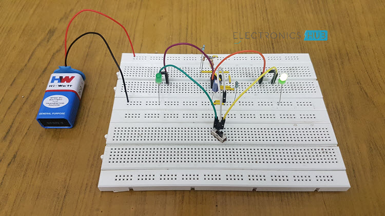
Bike Turning Signal Circuit Diagram
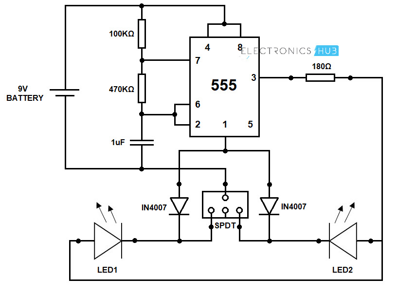
Circuit Components
- Resistor 180Ω
- Resistor 100KΩ
- Resistor 470KΩ
- Capacitor 1µF
- 555 Timer IC
- LEDs – 2
- Diodes (1N4007) – 2
- SPDT Slide Switch
- 9V Battery
- Connecting Wires
- Breadboard
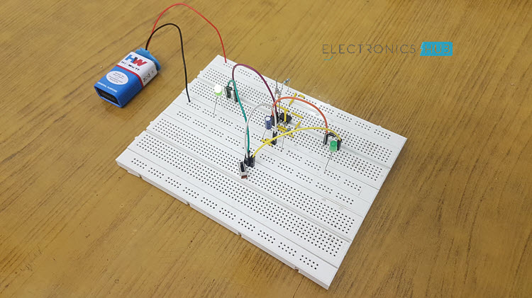
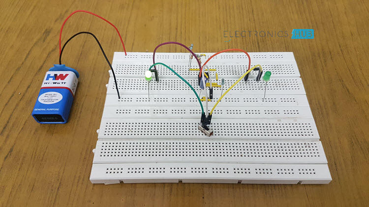
Bike Turning Signal Indicator Circuit Design
In this circuit, the 555 timer produces pulse signal with variable width. The pulse width is varied by varying resistance or capacitance value (100KΩ, 470KΩ or 1µF). Pins 2 and 6 are shorted to allow triggering after every timing cycle.
Fourth pin is reset, it is shorted with VCC (8th pin) to avoid sudden resets. 7th pin is discharging pin, it is connected to 6th pin through a 470KΩ resistor. The below figure explains you the operation of 555 timer. In this circuit capacitor C charges through resistors RA and RB. Now because of internal op-amps, capacitor C discharges through resistor RB. 555 timer internally consist of 2 operational amplifiers, one D flip flop and one NPN transistor.
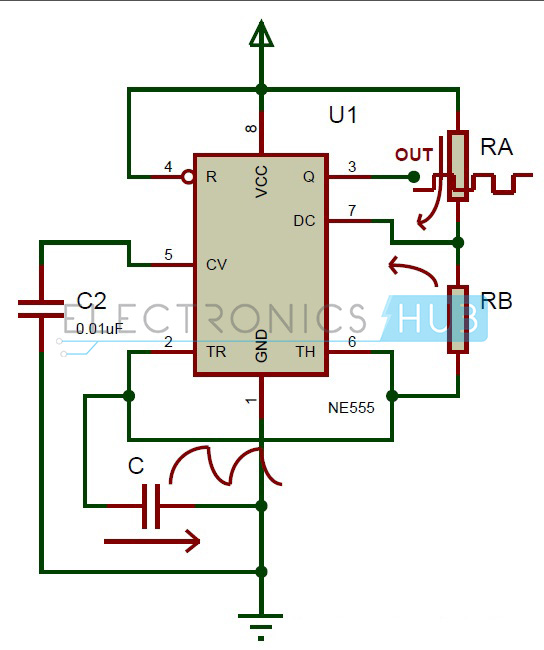
In the above circuit, the pulse is generated at the 3rd pin of the 555 timer. By varying the values of RA, RB or C, we can vary the pulse width. The total time period of the pulse is given as
T = THIGH + TLOW = 0.693 (RA+ 2RB) C
Frequency of the pulse is given as
f = 1/T = 1.44/ (RA+ 2RB)C
percentage of duty cycle is given as
% duty cycle, D = tc / T * 100 = (RA + RB) / (RA + 2RB) * 100
The obtained pulse from the 555 timer is applied to the LEDs through the slide switch to make the LEDs ON and OFF with some delay. Here the operating voltage of LEDs is around 2 to 3v but from battery, we get 9V supply. So, we need to drop the remaining voltage. To drop this voltage, we are using resistors in series with LEDs.
How to Operate the Circuit?
- Initially feed 9V power supply to the circuit.
- Slide the switch to the Left position and you can observe the LEFT Indicator LED will start to Blink with some delay.
- If you slide the switch to Right Position, the RIGHT Indicator LED will Blink.
- If you slide the switch to center, both the LEDs will be OFF
- If you want, set the different time delays for LEDs, then vary the resistance or capacitance value.
- Now you can see the change in time delay.
- By varying the capacitance value also you can see the in time delay of LEDs.
NOTE: Since this is a demonstration, I have used only one LED per channel (LEFT and RIGHT). But if you want to integrate several LEDs per channel, you can do that with the help of a Transistor on each channel and sufficient power supply.
Applications of Bike Turning Signal Indicator Circuit
- It is used to indicate left turn or right turn for a motor bike or vehicle.
- We can also use this circuit as an LED knight rider circuit.
- We can give it as a gift for the children.

4 Responses
how can this circuit be used to sense the right or left turn of bikes….. it just makes the leds to glow with a delay
what type of motherboard is that.
That’s not a motherboard, its called a breadboard, its used for prototyping sir-cutes. Also on the above sir-cute, it looks like the last LED’s don’t even come on. Way too slow, and to much delay. Its just a fade circuit (sur-kit). Close, but no cigar. I do like the fact that the first one stays lit when the other is trying to light, kind of like a mustang turn signal. Please revise and make like a mustang tail light turn indicator, then that’s success!! You could use a pair of switches for the left/right direction and take the top row and place beside for the left.
1. What circuit component would you change to vary the LED flash rate?
2. And where about on the bicycle would the control be mounted?
3. Where would the power source be kept?
4. Where would the LEDs be mounted?
5. What power should the LEDs be? What colour? How would this be tested? On the road?
6. Would this do away with other signalling methods?
7. How reliable will it be?
8. How would you know, when riding the bicycle that they are working?
9. In the worse case senario, what could happen if this device failed?
10. Would you recommend putting this on a child’s bicycle?