In this project, we will build few simple LED Circuits. Nowadays, people are investing more in LEDs due to their energy efficiency. Home lighting, office lighting, Automobile lighting, Street lighting etc. are all being implemented using LED.
Students, hobbyists and makers often work with LEDs in different types of projects. Some of the common LED projects are LED Running Lights, LED Light Bulb, LED Knight Rider and LED Flasher.
Simple LED Circuits
LEDs are very sensitive components with respect to voltage and current and they must be provided with rated current and voltage values. Beginners in electronics often start with LEDs and the first project would be blinking an LED.
Wrong voltage or current to LED will burn them off. For small projects like blinking an LED, we need not worry about burning LEDs as we can connect a small resistor (like a 330Ω) in series with the LED (for a 5V supply).
But as the complexity of the circuit increases, choosing the right resistor with right wattage is important. So, in this project, which is more of a tutorial, we will build some simple LED circuits like a simple single LED Circuit, LEDs in series, LEDs in parallel and high power LEDs.
Circuit 1 of Simple LED Circuits (Single LED Circuit)
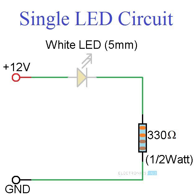
The first circuit in the simple LED Circuits is a single LED Circuit. We will try to turn ON a single 5mm White LED using a 12V Supply. The circuit diagram for this circuit is shown below.
Components Required
- 12V Power Supply
- 5mm White LED
- 330Ω 1/2W Resistor
- Connecting Wires
- Breadboard
Principle of Operation
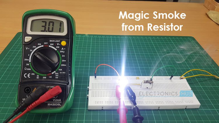
The following image shows the setup of single LED connected to a 12V Supply and a current limiting series resistor. The important component (other than the LED of course) is the Resistor. Connecting a small LED to a 12V Supply would burn the LED and you can see the magic smoke instantly.
So, selecting the right resistor with the right wattage is very important. First, we will calculate the resistance.
Calculating Series Resistor
The value of the series resistor can be calculated using the following formula.
RSERIES = (VS – VLED) / ILED
Here, VS is the Source or Supply Voltage
VLED is the voltage drop across the LED and
ILED is the desired current through the LED.
In our simple LED Circuit consisting of a single LED, we have used a 5mm White LED and a power supply of 12V.
As per the datasheet of the 5mm White LED, the Forward Voltage of the LED is 3.6V and the Forward Current of the LED is 30mA.
Therefore, VS = 12V, VLED = 3.6V and ILED = 30mA. Substituting these values in the above equation, we can calculate the value of Series Resistance as
RSERIES = (12 – 3.6) / 0.03 = 280Ω. Since there won’t be a 280Ω Resistor, we will use the next big resistor i.e. 330Ω. Hence, RSERIES = 330Ω.
Now that we have calculated the resistance of the series resistor, the next step is to calculate the power rating of this resistor.
Calculating Resistor Power
Power Rating of a Resistor specifies the value of power that a resistor can safely dissipate. The Power Rating of a Resistor can be calculated using the following formula.
PRES = VRES * IRES
Here, VRES is the voltage drop across the resistor and
IRES is the current through the Resistor.
We know that supply voltage is 12V and Voltage drop across LED is 3.6V. So, the Voltage Drop across the Series Resistor is
VRES = 12 – 3.6 = 8.4 V.
The current through the Resistor is same as the current through the LED as they are series. So, the current through the Series Resistor is
IRES = 30mA.
Substituting these values in the above formula, we get the power dissipated by the resistor.
PRES = 8.4 * 0.03 = 0.252 Watts.
To be on the safe side, we always have to pick the next possible value and hence we have chosen a ½ Watt (0.5 Watt) Resistor.
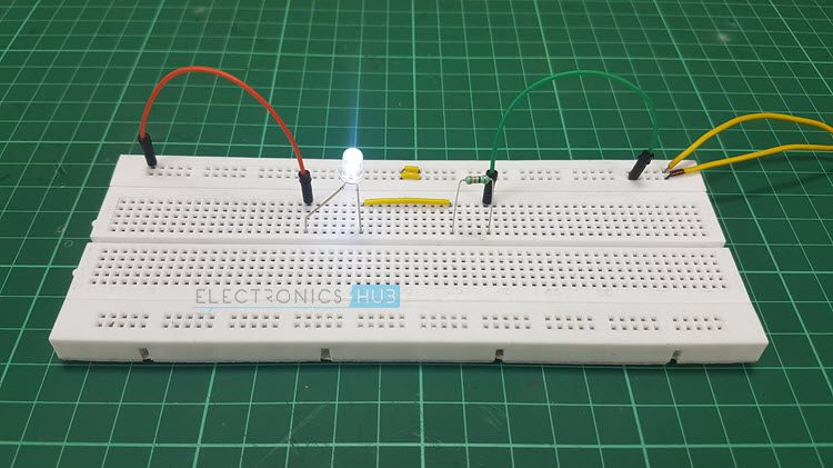
Once the right resistor is selected, we can connect the resistor in series and give the 12V Supply to the LED.
Circuit 2 of Simple LED Circuits (LEDs in Series)
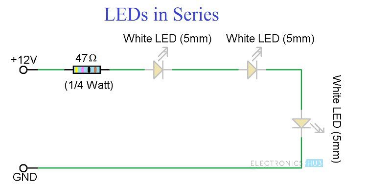
The next circuit in the Simple LED Circuits project is connecting LEDs in series. In this circuit, we will connect three 5mm White LEDs is series with the same 12V Supply. The following image shows the circuit diagram of the LEDs in Series.
Circuit Diagram of LEDs in Series
Components Required for LEDs in Series
- 5mm White LEDs x 3
- 47Ω Resistor (1/4 Watt)
- 12V Power Supply
- Connecting Wires
- Breadboard
Principle of Operation
Since the LEDs are connected in Series, the current through all of them will be the same i.e. 30mA (for 5mm White LED). As three LEDs are connected in series, all the LEDs will have a voltage drop of 3.6V i.e. each LED will have a voltage drop of 3.6V across it.
As a result, the voltage drop across the resistor will fall down to 12 – 3*3.6 = 1.2V. From this, we can calculate the resistance as R = 1.2 / 0.03 = 40Ω. So, we have to choose 47Ω Resistor (the next available one).
Coming to the power rating of the resistor, it is equal to 1.2 * 0.03 = 0.036. This is a very low power rating and the minimum available one is of ¼ Watts.
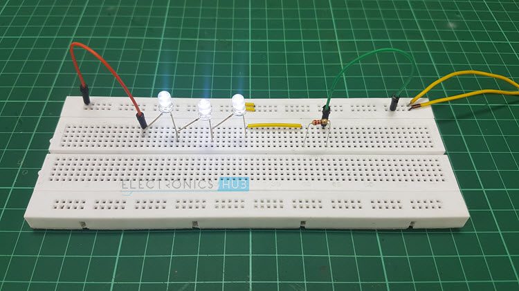
Once all the components are selected, we can connect them on a breadboard and power on the circuit using a 12V Supply. All the three LEDs in Series will light up with maximum intensity.
Circuit 3 of Simple LED Circuits (LEDs in Parallel)
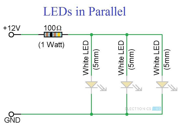
The final circuit in the simple LED Circuits tutorial is LEDs in Parallel. In this circuit, we will try to connect three 5mm White LEDs in parallel and light them up using a 12V Supply. The Circuit Diagram for LEDs in Parallel Connection is shown in the following image.
Circuit Diagram of LEDs in Parallel
Components Required for LEDs in Parallel
- 12V Power Supply
- 3 x 5mm White LEDs
- 100Ω Resistor (1 Watt)
- Connecting Wires
- Breadboard
Principle of Operation
For LEDs connected in Parallel, the voltage drop across all the LEDs will be 3.6V. This means that the voltage drop across the Resistor is 8.4V (12V – 3.6V = 8.4V).
Now, since the LEDs are connected in parallel, the current required for all the LEDs is equal to three times that of the individual current through the LED (which is 30mA).
Therefore, the total current in the circuit is 3 * 30mA = 90mA. This current will also flow through the resistor. Hence, the value of the resistor can be calculated as R = 8.4 / 0.09 = 93.33Ω. The nearest higher resistance value is 100Ω.
The Power dissipated by the resistor is given by 8.4V * 0.09A = 0.756Watts. As the next higher wattage is 1W, we have used a 1Watt Resistor.
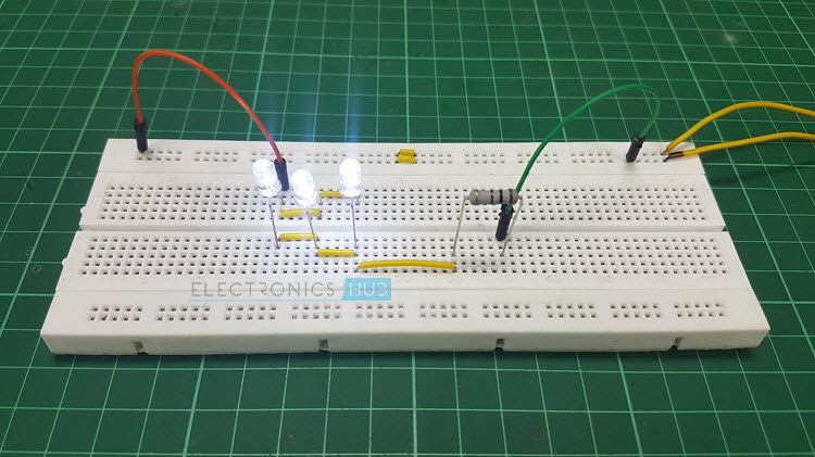
Connect the three LEDs in Parallel and also connect the 100Ω (1 Watt) Resistor in series with the power supply. Up on turning on the supply, all the LEDs will light up.
Additional Circuits
- Here is a 23V0V LED Driver Circuit. In this circuit, we will drive an LED directly from 230V AC Mains Supply.
Warning: It is very dangerous to use 230V AC Supply on breadboard. Be extremely careful.
- Another interesting LED circuit is the DIY LED Light Bulb. In this, we designed an LED Light Bulb and used it as a regular bulb.
Warning: Even this project uses 230V AC for powering the LED Light Bulb. Be cautious when handling mains supply.

8 Responses
hi
iam AravindManoj a computer engineering student
please help mwe to build a project
for my aquarium
10watt led chip x 20 led lights
i dont know what resistor or capacitor please help
Give details of led size, colours used, circuit to be used, parallel or series
12V , 2A Power Supply.
15, 1W LEDs nominal is 3.2V forward volatage and 310mA is the current.
I need to drive the LED to around 3.4V current is 400mA to get the maximun out of it,
What will be the connections? and resistor values
Thanks in Advance
Very nicely and cleared explain with circuit diagram. Thanks
Tnx
Hello, what if not resistance is installed when Diodes are in series with a 12v dc power supply?
Can flashing LED’s in parallel be used instead of those that do not flash?
Can a lower voltage power supply be used?
Can surface mount components be used?
Hello
I am looking to put 4 led Edison bulb filaments in parallel using a USB power brick and USB cable. The led’s come in 3v 100ma and 12v 45ma options. I would like to know what power brick to use and what resister I would need. I have a 9v 1.67a or 5v 2a power brick at home but could get a different one if needed. This is for a diorama with plastic models that one led will be running through. Any help would be greatly apriciated.