In this tutorial, we will learn about a simple yet interesting concept called the 2 Way Switch Wiring Diagram. It is also called as a Staircase Switch, as you can control a single load, a light bulb for example, from two different places, like either ends of a staircase.
WARNING: This is just a theory explaining how does a two way light switch works. It is not an user guide on how to install or wire a 2-way switch. If you are planning to implement a similar setup in your home, then definitely consult a professional as the process involves working with 230V AC Supply (or 110V AC, depending on where you live).
Two Way Switch Wiring Diagram
We use switches all the time in our homes, offices, cars, industries and many other places. The gadgets we use daily (mobile phone and laptop) consists of several switches. A Switch is an electrical device which is used to open or close an electric circuit.
There are different types of switches like Toggle Switch, Momentary Switch, Rocker Switch, Digital Switch, etc. All the switches perform simple task of either interrupting the flow of electric current or divert the flow of current. They essentially ‘make’ or ‘break’ the circuit.
All the switches we use regularly to turn on or off lights, fans, etc. are two terminal devices. But there is a special switch called ‘Two Way Switch’, which is the an important component in the implementation of Staircase Lighting.
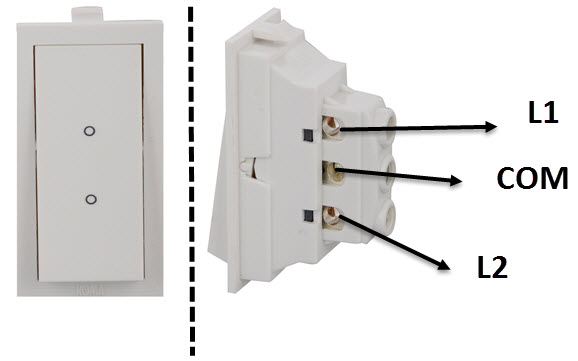
So, before proceeding to learn about the wiring of a two way switch connection, we will learn about the Two Way Light Switch, which is the main element of the 2 Way light Switch wiring, irrespective of the type of wiring used. It is a standard single pole double throw switch with three terminals.
The three terminals are usually named COM, L1 and L2, but sometimes the terms COM, 1 Way and 2 Way are also used. In one position, the COM and L1 terminals are connected, while in the second position, the COM and L2 terminals are connected.
This type of connection is typically called a “Break before make” design, as the first connection has to be broken before making the second connection. This is in contrast to a regular two terminal switch, which is just a make or break device.
The following 2 way light switch wiring diagram shows the front and back view of a typical household two-way switch.
How To Wire 2 Way Switch?
A 2 way light switch wiring is very useful in staircase lighting as you can turn on the light just before you start to climb the stairs and once you reach upstairs, you can turn off the light simply by toggling the switch placed near the top of the staircase.
There are a couple of ways in which you can make a two way switch connection. One is an older method, which is not often used now-a-days and the other is a more modern and safer version, which is being implemented in industrial as well as residential applications. Let us take a look at both these wirings.
Standard 2 Way Switch Wiring Diagram
The first way of wiring uses a couple of Two-Way Light Switches with a three wire control (3 Wire Control). The following is the simple schematic of a wiring diagram for 2 way light switch

You can observe in the schematic that both the COM terminals are connected together. The L1 terminals of both the switches are connected to line (or phase or live) of the AC Supply.
The L2 terminals of both the switches are connected to one terminal of the light bulb, while the other terminal of the light bulb is connected to the neutral of the AC power supply.
From the schematic, you can easily visualize how the wiring works. In the default state shown in the above image, the light is off. If either of the switches is toggled, the light turns on. To turn off the light, you can toggle any switch.
For example, in the above state, the COM terminals of both the switches are connected to respective L1 terminals. Now, if we toggle Switch 1 i.e., COM of Switch 1 is now connected to its L2 terminal, then there is a path to complete the circuit and the light turns on.
To turn off the light, we can toggle either Switch 1 or Switch 2 as any toggling action will break the flow of current to the light. So, considering all the possibilities, the light is on in two cases:
- COM of Switch 1 is connected to L1 and COM of Switch is connected to L2.
- COM of Switch 1 is connected to L2 and COM of Switch is connected to L1.
If we compare this setup with digital electronics, then this is similar to an Ex-OR Gate, where the status of the light (ON or OFF) depends on the status of the COM terminals of both the switches connected to respective L1 and L2 terminals.
The following table shows the truth table for Standard Wiring i.e., 3-Wire Control of Two Way Switch Connection, where the output (status of the light) depends on what terminal (L1 or L2) is connected to the COM terminal.
This method is recommended as both the line and neutral wires come from the same lighting circuit (or breaker) even though it uses more wire.
Alternative Method of Two Way Switch Wiring
The next wiring design is an old system which you might find in some older homes and industrial settings. It is also called as two wire control wiring (2 Wire Control).
This wiring system is not recommended for modern implementations and if you are planning to install a new setup or replace an older one, then the previous wiring must be used.
I have included the alternative wiring method just as a reference and I will also explain its drawbacks.
Coming to the actual wiring, the following schematic shows the implementation of a two-wire control two-way switch.
Two Way Switch Diagram
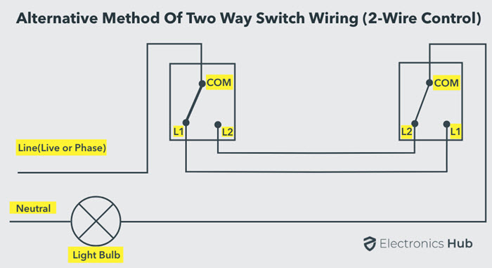
L1 terminals of both the switches are connected together and L2 terminals of both the switches are also connected together. Coming to the COM terminals, the COM terminal of the first switch is connected to phase (or line or live).
The COM terminal of the second switch is connected to one end of the light bulb while the other end of the light bulb is connected to the neutral of the AC Supply.
In the default state (as shown in the schematic), the light is off. But when either of the switches is toggled, then the light turns on. In terms of digital electronics, this configuration is similar to an Ex-NOR Gate.
The following table shows the truth table for Alternative Method Wiring i.e., 2-Wire Control of Two Way Switch
Even though this method saves cable, it is not being preferred anymore as the Phase and Neutral may come from different lighting circuits (or breakers).
Another major flaw is with respect to electromagnetic interference. We know that any current carrying conductor emits electromagnetic radiations. If the Live and Neutral wires are placed in close proximity, they cancel each other’s EM Radiation.
But in this wiring, there is possibility that the neutral and live wires are being run separately at different parts of the house, making the wires a giant induction loop. This will definitely cause interference problems with other EM and RF Signals.
2 Way Switch Diagram Example
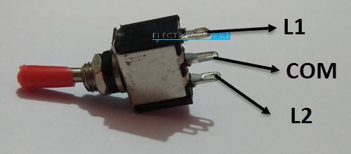
I do not have Two-Way Light Switches to demonstrate the working but I thought I would make a similar setup using a couple of Single Pole Double Throw (SPDT) Toggle Switches and an LED (as essentially, a two way switch is an SPDT Switch).
The SPDT Toggle switch can be considered as a Two-Way Light Switch as it has three terminals and works very similar to the two-way light switch.
The following image shows a typical SPDT Toggle switch with its terminals.
For wiring, I selected the standard way of wiring (the first method i.e., the 3-wire control) with a 3.7V Lithium-Ion Battery as the power supply. It worked flawlessly.
Conclusion
A complete beginner’s guide on two way switch, working of two way switch wiring, different types of wiring for two way switch or Staircase Wiring and also the schematic for the wiring.

19 Responses
This is wonderful
Well understood
I love all this work
Helpful
Thank you for great information
Thank you this explains how it works in simple terms.
I love it, it’s interesting
Think you for sharing this wonderful information .
Wow! This is simply awesome! Very interesting and easy to understand. Thank you very very much.
Thanks for your information but the one I get problem with is the connection in the junction box… A not too clear okay… Please show the wire and function okay
Thanks alot????
God bless you ????
Thanks… Genius explanation. Just couldn’t for the life of me work it out myself! 😀
As a complete beginner, I love this. I understand the old way but need to get my head around the new way.
Thanks amillion I love it so sweet.
Very good explanation.
Thank you.
I found this while struggling to find out how electricians had wired my 2-way lighting.
There were two 2-way lighting setups.
I can see that they used one method for one and the second on the other.
One was a conventional landing light where the lamp was close to the switch, the other a lamp in the middle of a hallway with switches at each end.
It was wired using in UK terms, 3&E, or a cable with three cores and earth,
Two cores were used for the switching and the third core was used to supply a neutral from one switch position to the lamp, cut in the middle and the other half of the core used to supply the switched live to the lamp.
It worked, but very poor wiring practice, like using the protective earth as a spare conductor.
Principles and regulations have to be followed.Thanks very mch.
This is very much useful. We must need to decide which connection to be used.
Its incredible thank you
Good theory.i love this as an electrician.God bless you all