In this tutorial, I will show you how to design and build a simple 555 LED Flasher Circuit. I implemented this LED Flasher circuit in such a way that it mimics a Police Flasher instead of a simple ON-OFF sequence.
555 LED Flasher Circuit
555 Timer IC is one fascinating integrated circuit. There are many configurations and implementation of 555 Timer IC like Astable Multivibrator, Bistable Multivibrator, Monostable Multivibrator, Schmitt Trigger, PWM Generation, LED Blinking, and many more.
One such application of 555 Timer IC is LED Flasher. In its simplest form, an LED Flasher simply flashes an LED i.e., a continuous sequence of LED going ON-OFF. By modifying this implementation, you can build a better-looking LED Flashing Circuit, which will identical to Police Flasher Lights.
555 LED Flasher Circuit Diagram
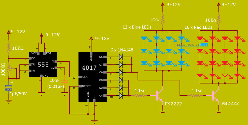
The following image shows the circuit diagram of 555 based LED Flasher. I modified the pins on both the ICs (555 and 4017) to simplify the circuit connections. I placed the appropriate pin number adjacent to the pin in the circuit diagram.
Components Required
- 555 Timer IC
- CD4017 Decade Counter IC
- 12 x 5mm Blue LEDs
- 16 x 5mm Red LEDs
- 3 x 10 KΩ Resistors
- 1 x 100Ω Resistor
- 1 x 22Ω Resistor
- 1 x 100 KΩ Potentiometer
- 1 x 1µF Capacitor
- 1 x 10nF Capacitor (0.01µF – 103)
- 6 x 1N4148 Fast Switching Diode
- 2 x PN2222 NPN Transistor
Hardware Connections
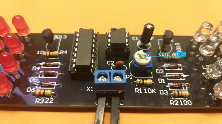
I designed a PCB for 555 LED Flasher Circuit using 4017 IC.

If you worked on 555 Timer PWM related Projects, then the 555 part of the above circuit will be a familiar one. Pins 4 and 8 of the 555 Timer IC i.e., RESET and VCC are connected to supply, which can any voltage between 9V and 12V.
A 10 KΩ resistor is connected between VCC and Pin 7 of 555, which is the DISCHARGE pin. A 100 KΩ Pot is connected between Pins 7 and 6, which is the THRESHOLD pin. Also, pin 2 of 555, which is the TRIGGER pin is connected to pin 6.
Comping to the main charge / discharge capacitor, a 1µF capacitor is connected between Pin 6 of 555 Timer IC and ground. Speaking of ground, pin 1 is the GND pin and is connected to ground.
Pin 5, which is the CONTROL VOLTAGE pin, is not used and hence a 10nF capacitor is connected between pin 5 and ground.
The OUTPUT pin i.e., Pin 3 of 555 Timer IC is connected to Pin 14 of 4017, which is the CLOCK input pin. Pin 16 of 4017 is connected to supply and pins 8, 13 and 15 (VSS, CLOCK INHIBIT and RESET) are connected to ground.
I chose 6 outputs of 4017 to flash the LEDS. Outputs 0, 2 and 4 (Pins 3, 4 and 10) are controlling Red LEDs while outputs 5, 7 and 9 (Pins 1, 6 and 11) are controlling Blue LEDs. All the 6 outputs are connected to respective 1N4148 Fast Switch Diodes.
The forward voltage of 5mm Red LED is 2V while it is 3.2V for 5mm Blue LEDs. So, I connected 3 Blue LEDs in series and four such sets in parallel to a PN2222 NPN Transistor.
Coming to Red LEDs, I connected 4 Red LEDs in series and four such sets in parallel to another PN2222 Transistor. Blue LED Transistor is driven by outputs 0, 2 and 4 of 4017 IC while Red LED Transistor is driven by outputs 5, 7 and 9 of 4017.

Working
In the previous 555 Timer Project, I designed a simple 555 Timer PWM Generation Circuit. If you are interested in PWM generation, then take a look at that project.
Coming back to this project, it can be considered as an extension to the PWM project as essentially the 555 Timer is operating in Astable Mode.
I also explained how 555 Timer IC works in Astable Mode in that tutorial. Instead of the Duty Cycle aspect of the Astable Multivibrator, we are interested in its Frequency aspect.
Based on the above-mentioned components, the frequency of the output pulse varies from 6Hz to 150Hz (approximate values). The output of the 555 Timer IC is supplied as clock input to the 4017 Decade Counter IC.
Whenever there is a LOW to HIGH transition on the clock signal i.e., on the rising edge, the output of the counter is incremented by 1. Since we are changing the frequency of the output of the 555 Timer (which is the clock of 4017), we are changing the rate at which the outputs are incremented.
Outputs 0, 2 and 4 are connected to a bunch of Blue LEDs while outputs 5, 7 and 9 are connected to a bunch of Red LEDs.
Conclusion
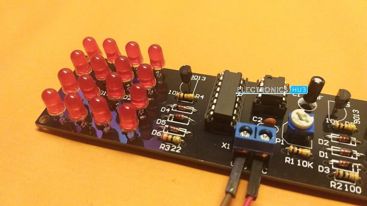
A simple 555 LED Flasher Circuit is implemented in this project. You can easily build this flasher circuit as a DIY project or as a 555 Timer IC learning kit.
