In this tutorial, I will show you how to use I2C in STM32F103C8T6 MCU based STM32 Blue Pill Board. To demonstrate the I2C Communication, we need atleast one Master and one Slave. So, in this STM32 I2C Tutorial, I will be using an STM32 MCU as Master and an Arduino UNO as Slave.
Introduction
We have already seen several I2C Communication related projects implemented with Arduino. Let us quickly recall some critical information about I2C Protocol. I2C, which is short for Inter Integrated Communication, is developed by Phillips as a simple two wire serial communication protocol for data transfer between Microcontroller and some low speed peripherals like Memory, Timers, Sensors, IO, ADC, DAC etc. at a short distance.
Almost all modern Microcontrollers feature built-in I2C Communication Protocol system. I2C is a multi-master multi-slave protocol that need only two wires viz., SDA (Serial data) and SCL (Serial Clock) for communication (there should be a common GND).
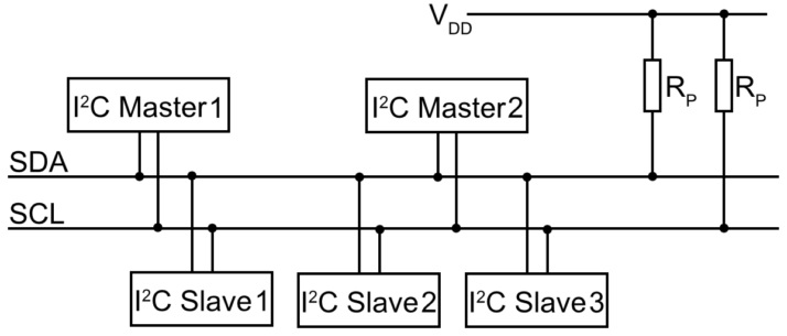
An important thing to remember is that the two wires are in open drain configuration and must be pulled HIGH with appropriate pull-up resistor to be able to drive logic HIGH on the bus.
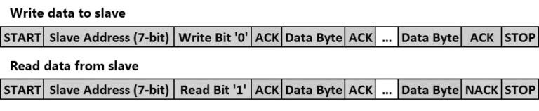
The I2C Communication starts when the master initiates the START condition, where the SDA line goes from HIGH to LOW while the SCL line in HIGH. This is followed by a 7-bit slave address and a single bit indicating a read (‘1’) operation or a write (‘0’) operation.
I2C in STM32F103C8T6
STM32F103C8T6 MCU has two I2C Interfaces namely I2C1 and I2C2. Both the I2C Interfaces support standard communication speed i.e. 100KHz as well as fast communication speed i.e. 400KHz.
The pin mapping for both the I2C Interfaces in STM32 Blue Pill is mentioned below:
- I2C1
- SDA – PB7 or PB9
- SCL – PB6 or PB8
- I2C2
- SDA – PB11
- SCL – PB10
In this project, I will be using PB7 as SDA and PB6 as SCL.
I2C in Arduino
Since we need a slave device for I2C Communication, we can use any famous I2C devices like DS1307 RTC IC, PCF8574 GPIO Expander IC, AT24XX EEPROM IC, etc. But in this project, I will use Arduino UNO as the I2C Slave Device so that we can make a to and fro communication between STM32 and Arduino.
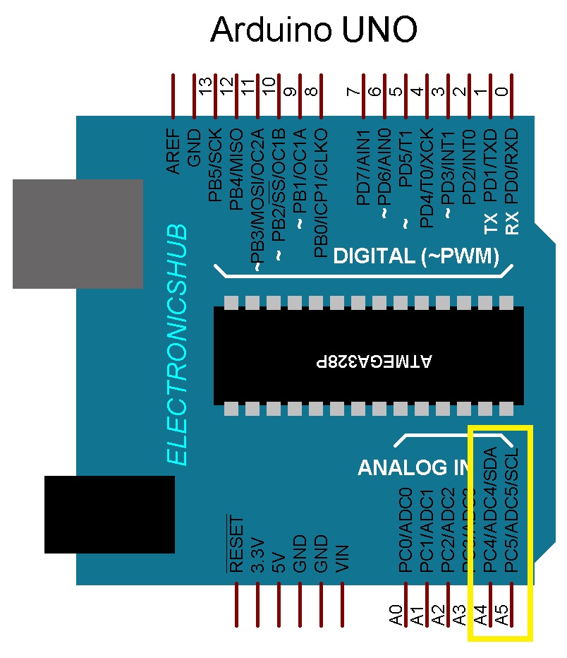
Speaking of I2C in Arduino, Pins A4 and A5 are I2C Communication Pins in Arduino UNO where A4 is the SDA Pin while A5 is SCL Pin.
Components Required
- STM32F103C8T6 MCU based STM32 Blue Pill Board
- Arduino UNO
- 2 x 5mm LEDs
- 2 x 220Ω Resistors
- 2 x 4.7KΩ Resistors
- 2 x 10KΩ Resistors
- 2 x Push Buttons
- Connecting Wires
- USB to UART Converter (if programming through UART)
Circuit Diagram
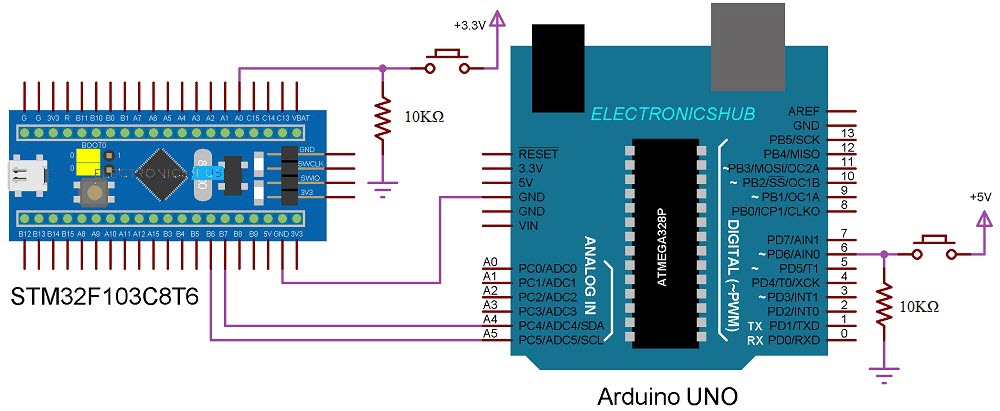
The following image shows the circuit diagram of using I2C in STM32F103C8T6 to communicate with Arduino over I2C Bus.
Connections Explained
The connections for demonstrating the use of I2C in STM32F103C8T6 is very simple. Connect the SDA pin of STM32 i.e. PB7 with corresponding SDA pin of Arduino i.e. A4. Similarly, connect the SCL pin of STM32 i.e. PB6 to corresponding SCL pin of Arduino i.e. A5. Pull the SDA and SCL pins HIGH using two 4.7KΩ resistors.
Now, connect a push button to PA0 pin of STM32 and also pull this pin to GND using a 10KΩ resistor. Connect the other end of the push button to 3.3V.
Repeat the same thing for Arduino i.e. connect a push button to Digital IO pin 6 and pull this pin to GND using a 10KΩ resistor. Connect the other end of the push button to 5V.
We can use the on-board LEDs of both the boards, which are connected to PC13 in STM32 and Digital IO pin 13 in Arduino. Make sure that GND of both Arduino and STM32 is made common.
Programming STM32 for I2C Communication
First, let us start with the I2C Master device i.e. the STM32. Define the LED pin and Button Pin as PC13 and PA0. Also, define the Slave Address of Arduino as 0x8. Initialize the pins i.e. LED Pin as OUTPUT and Button Pin as INPUT and begin the I2C Communication.
In the loop function, divide the operation into two parts i.e. one for reading the button pin and sending corresponding data and the other part for reading the incoming data and turning the LED ON or OFF (based on the received data).
Code
#include <Wire.h>
#define LEDPIN PC13
#define BUTTONPIN PA0
#define SLAVEADDRESS 0x8
int sendData = 0;
void setup()
{
pinMode(BUTTONPIN, INPUT);
pinMode(LED, OUTPUT);
Wire.begin();
}
void loop()
{
int buttonValue = digitalRead(BUTTONPIN);
Wire.requestFrom(SLAVEADDRESS, 1);
byte readData = Wire.read();
if (readData == 1)
{
digitalWrite(LED,HIGH);
}
else
{
digitalWrite(LED,LOW);
}
if(buttonValue == HIGH)
{
sendData = 1;
}
else
{
sendData = 0;
}
Wire.beginTransmission(SLAVEADDRESS);
Wire.write(sendData);
Wire.endTransmission();
delay(500);
}
Programming Arduino for I2C Communication
Now coming to Arduino, it must be configured as Slave device. First, define the LED Pin as Digital IO pin 13 and Button Pin as Digital IO pin 6 and initialize them as OUTPUT and INPUT respectively.
Since, Arduino is the slave, we must begin the I2C Communication by using the slave address. This address must be same as the one defined in the master code (or vice-versa) i.e. slave address mentioned in Slave Code and Master Code must match.
Another important thing to remember is a Slave in I2C Communication cannot initiate the transfer and it can only comply with read or write requests from the master.
Hence, if the master performs a read operation, then Wire.onRequest function is called and this in turn calls the specified requestFun.
Similarly, if a write operation is initiated by the master, the Wire.onReceive function is invoked which in turn will call the receiveFun.
Code
#include <Wire.h>
#define LEDPIN 13
#define BUTTONPIN 6
#define SLAVEADDRESS 0x8
byte sendData = 0;
void setup()
{
pinMode(LED,OUTPUT);
Wire.begin(SLAVEADDRESS);
Wire.onReceive(receiveFun);
Wire.onRequest(requestFun);
}
void loop()
{
delay(100);
}
void receiveFun (int bytes)
{
byte recvData = Wire.read();
if (recvData == 1)
{
digitalWrite(LED,HIGH);
}
else
{
digitalWrite(LED,LOW);
}
delay(500);
}
void requestFun()
{
int buttonValue = digitalRead(buttonpin);
if (buttonValue == HIGH)
{
sendData = 1;
}
else
{
sendData = 0;
}
Wire.write(sendData);
}
Conclusion
A simple project for demonstrating I2C in STM32F103C8T6 MCU based STM32 Blue Pill Board. The STM32 is acting as master in the I2C Communication while Arduino UNO is used as a slave device.
When a button is pressed in the master i.e. STM32, an LED will light up in Arduino. Similarly, when a button is pressed in Arduino, an LED in STM32 will light up.

One Response
Do you have to do anything to tell the arduino which pins are the desired I2C pins since there is more than one set of pins which can be used?