In this tutorial, I will show you how to use ADC in STM32F103C8T6 Blue Pill Board to measure the Input Analog Voltages. I have already shown you how to interface a 16×2 LCD with STM32 Blue Pill in a previous tutorial. I will use the LCD to display the results of ADC in this project.
Introduction
Almost all embedded applications require at least one Sensor to be interfaced with the Microcontroller. It may be a Temperature Sensor or a Position Sensor. If we know one thing about Sensors it is that almost all Sensors (in its basic form) are analog in nature. What this means is that a Sensor reads an Analog Value from the nature (like Temperature) and produce an Analog Voltage.
But the problem with Microcontrollers (be it STM32F103C8T6 or Arduino) is that they are digital “beings” and cannot work with Analog values. Hence, we have to first convert the analog value into Digital values before giving them to the Microcontroller for further processing or analyzing. Analog to Digital Converters are used for this purpose.
If you worked with 8051 Microcontrollers, then you probably might have used an external ADC IC like ADC0804 IC to convert input Analog signal to digital values. But most modern Microcontrollers like Arduino or STM32F103C8T6 have ADC built into them. Hence, we do not need any external components. All we have to do is configure the internal ADC and convert the analog values to digital values.
In this project / tutorial, I will demonstrate how to interface a potentiometer, which is the simplest source of variable analog voltage, and configure an Analog Pin to read the voltage, use the ADC to convert it to a digital value and display the result on LCD.
ADC in STM32 Blue Pill
If you refer to the data sheet of STM32F103C8T6 MCU, then you can see that the ADC of STM32F103C8T6 MCU is of 12-bit resolution and is a Successive Approximation Type ADC. The MCU supports up to 16 external Channels for measuring Analog Signals.
But the ADC in STM32 Blue Pill board is configured for 10 Channels i.e. you can use the 10 Analog Input pins to measure 10 different analog voltages.
How to use ADC in STM32F103C8T6?
As mentioned earlier, the ADC in STM32 Blue Pill has a resolution of 12-bits. So, the range of ADC values in STM32F103C8T6 is from 0 to 212 – 1 i.e. 0 to 4095. Based on the analog voltage, the value will increase in steps.
The voltage / Step or the resolution can be calculated using the following formula.
Voltage / Step = Reference Voltage / 212
The reference voltage is usually 3.3 V. Hence, the smallest change in voltage that can be detected is
Voltage / Step = 3.3 / 4096 = 0.8056 mV / Step
Now, the Input Analog Voltage can be calculated as follows:
Input Voltage = ( ADC Value / ADC Resolution ) * Reference Voltage
Circuit Diagram
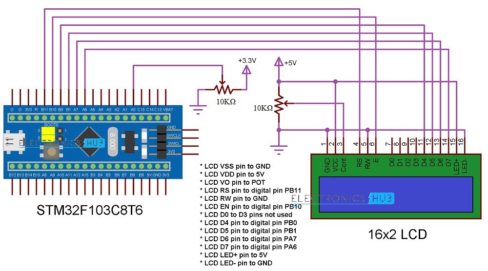
The following image shows the circuit diagram of the project for configuring ADC in STM32F103C8T6.
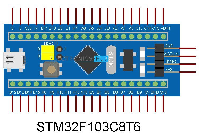
If the pins of the STM32 Blue Pill Board used in the circuit diagram are not clear, then use the following image as reference.
Components Required
- STM32F103C8T6 MCU based STM32 Blue Pill Board
- 16×2 LCD Display
- 10KΩ POT x 2
- USB to UART Converter (if programming through UART)
- Connecting Wires
Circuit Explanation
As mentioned earlier, there are 10 Analog Inputs on the STM32 Blue Pill Board. They are PA0 to PA7 (ADC0 to ADC7) and PB0 and PB1 (ADC8 and ADC9).
You can use any of the Analog Input Channel in your project. For this demonstration, I will be using ADC0 i.e. PA0 pin as the analog input pin. To this pin, I have connected the center (wiper) terminal of a 10KΩ Potentiometer, while the other two terminals of the POT are connected to 3.3 V and GND.
I am using a 16×2 LCD display as an output device. In the “Interfacing 16X2 LCD with STM32F103C8T6” project, I have already explained the connections between STM32 Blue Pill Board and the 16×2 LCD. I am using the same connections here as well.
Programming STM32 Blue Pill
If you have already followed my “Program STM32 Blue Pill via USB” tutorial, then you do not need a USB to UART Converter as you can use the on-board USB to upload the program.
Speaking of the program, first, initialize pins for LCD and Analog Input. Then initialize the LCD and display some introductory information. In the loop section, read the analog voltage from analog input pin (PA0) using the analogRead function and store the value in a variable called analogVal.
Now, using the above-mentioned formula, you can calculate the input voltage. Use a Float variable to hold the value of the calculated input voltage.
float inputVoltage = ((float) analogVal) / 4096 * 3.3
Display the calculated Analog Voltage on the LCD along with the calculated ADC Value. You can continuously vary the POT and the corresponding analog voltage will be read by the ADC in STM32F103C8T6 and calculate the voltage.
Code
/*
* LCD VSS pin to GND
* LCD VDD pin to 5V
* LCD VO pin to POT
* LCD RS pin to digital pin PB11
* LCD RW pin to GND
* LCD EN pin to digital pin PB10
* LCD D0 to D3 pins not used
* LCD D4 pin to digital pin PB0
* LCD D5 pin to digital pin PB1
* LCD D6 pin to digital pin PA7
* LCD D7 pin to digital pin PA6
* LCD LED+ pin to 5V
* LCD LED- pin to GND
*/
#include <LiquidCrystal.h>
const int rs = PB11, en = PB10, d4 = PB0, d5 = PB1, d6 = PA7, d7 = PA6;
LiquidCrystal lcd(rs, en, d4, d5, d6, d7);
const int analogInput = PA0;
void setup()
{
lcd.begin(16, 2);
lcd.clear();
lcd.setCursor(0, 0);
lcd.print(“Electronics Hub”);
lcd.setCursor(0, 1);
lcd.print(” ADC in STM32 “);
delay(2000);
lcd.clear();
}
void loop()
{
int analogVal = analogRead(analogInput);
float inputVoltage = (float(analogVal)/4096) * 3.3;
lcd.setCursor(0, 0);
lcd.print(“ADC Value:”);
lcd.print(analogVal);
lcd.setCursor(0, 1);
lcd.print(“Voltage:”);
lcd.print(inputVoltage);
}
Conclusion
A simple demonstration of the working of ADC in STM32F103C8T6 MCU based STM32 Blue Pill board is implemented in this project.
