In this tutorial, I will show you How to use SPI in STM32F103C8T6 MCU based STM32 Blue Pill Board. For SPI Communication, we need one master device and one or more slave devices. Hence, for demonstrating SPI in STM32F103C8T6, I will be configuring STM32 as SPI Master and Arduino UNO as SPI Slave.
Introduction
SPI, which is short for Serial Peripheral Interface, is one of the frequently used communication protocols for transfer of data between a Microcontroller and a wide range of peripheral devices like Flash Memories, EEPROMs, SD Cards, Sensors, LCDs, etc.
A common way to implement SPI Communication is using four wires, although there are ways you can use lesser number of wires. In this tutorial, I will be using the four wire SPI Communication and the four wires are called as:
- SCLK -> Serial Clock
- MOSI -> Master Output Slave Input (Data from Master to Slave)
- MISO -> Master Input Slave Output (Data from Slave to Master)
- SS -> Slave Select
The following image shows the simple SPI Interface between a Master and a Slave. The image also shows the direction of the corresponding signals.
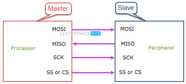
Slave Select Signal is used to activate a particular slave by making the SS signal as LOW. In a multi-slave configuration, each slave device has its own SS Signal from the Master and at any time, only one slave device can be active.
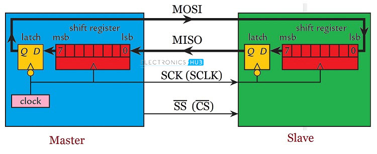
The internal hardware of SPI Communication is very simple. It consists of a Shift Register and a Data Latch. An important point to remember is that the Master device is responsible for generating the Clock Signal on the SCLK Line.
For more information on SPI Communication and its modes, refer to the “BASIC OF SERIAL PERIPHERAL INTERFACE” tutorial.
SPI in STM32F103C8T6
Coming to SPI in STM32F103C8T6 MCU, there are two SPI interfaces in this MCU and both can work in full duplex or simplex mode at speeds up to 18 Mbits/s. if you remember the pin configuration of the STM32 Blue Pill Board, you can see both the SPI Interfaces marked in purple colour.
For SPI1 Interface, there are two sets of pin configurations. The following table shows all the pins associated with SPI in STM32F103C8T6 MCU.
Alternative Pins SPI1 PA15 SCLK1 PB3 MISO1 PB4 PB5 SPI2 SCLK2 – MISO2 – –
SPI Signal
Pins
SS1
PA4
PA5
PA6
MOSI1
PA7
SS2
PB12
–
PB13
PB14
MOSI2
PB15
For the STM32 SPI Tutorial, I will be using the first set of pins of SPI1.
SPI in Arduino
As mentioned earlier, I am going to use Arduino UNO as the SPI Slave device. You can use any other SPI Devices like any Sensors or Memory ICs but I chose to use an Arduino as you can easily decode the SPI data and further do something extra like light up an LED or display the information on an LCD, which you cannot do with an EEPROM IC.
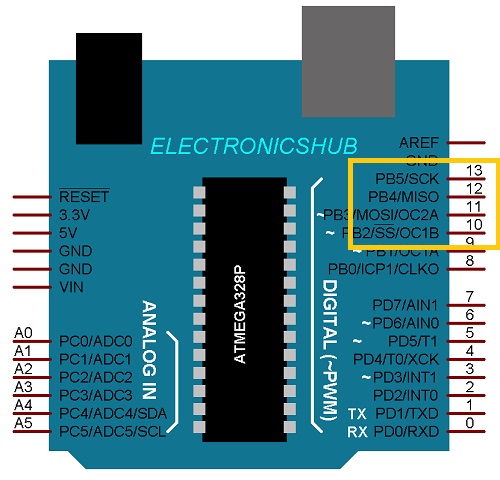
Speaking of SPI in Arduino, the Digital IO pins 10 through 11 are wired to the SPI Interface. The following table lists out the SPI pins in Arduino UNO.
SPI Signal Arduino Pin SS Digital IO 10 MOSI Digital IO 11 MISO Digital IO 12 SCK Digital IO 13
How to use SPI in STM32F103C8T6?
For demonstration of SPI in STM32F103C8T6, the STM32 Blue Pill Board is configured as SPI Master and Arduino UNO is configured as SPI Slave. Both the boards are connected with external Push Buttons and I will also use the on-board LEDs on each board.
When the Push Button connected to STM32 is pressed, the LED on Arduino will be turned ON. Similarly, when the Push Button connected to Arduino UNO is pressed, the LED on STM32 Blue Pill Board will be turned ON.
You can extend this project and use 16×2 LCDs with both STM32 Blue Pill Board and Arduino UNO and display some information.
Components Required
- STM32F103C8T6 MCU based STM32 Blue Pill Board
- Arduino UNO
- 2 x Push Buttons
- 2 x 10 KΩ Resistors
- Connecting Wires
- USB to UART Converter (if STM32 is programmed via UART)
- USB Cable for Arduino UNO
Circuit Diagram
The following image shows the connections between STM32 and Arduino to demonstrate STM32 SPI Tutorial.
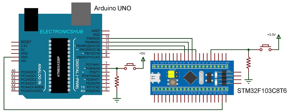
Connections Explained
First, make a note of the SPI Pins in both STM32 Board and Arduino UNO. Then connect the corresponding pins of each board i.e. MOSI pin on STM32 (PA7) to MOSI Pin on Arduino (Digital IO 11), MISO pin on STM32 (PA6) to MISO Pin on Arduino (Digital IO 12), SCLK pin on STM32 (PA5) to SCK Pin on Arduino (Digital IO 13) and SS pin on STM32 (PA4) to SS Pin on Arduino (Digital IO 10).
The following table shows the pins corresponding to SPI in both STM32 and Arduino UNO.
SPI Pin Arduino UNO SS Digital IO 10 SCLK Digital IO 13 MISO Digital IO 12 MOSI Digital IO 11
STM32 Blue Pill
PA4
PA5
PA6
PA7
Now, connect one end of a push button to PA0 pin of STM32. Also, pull this pin to GND using a 10KΩ resistor. Connect the other end of the push button to 3.3V. Repeat the same thing for Arduino i.e. connect one end of a push button to Digital IO pin 6 and pull this pin to GND using a 10KΩ resistor. Connect the other end of the push button to 5V.
Since I am going to use the on-board LEDs of both STM32 Blue Pill Board and Arduino UNO, there is no need for any additional components.
Programming STM32 for SPI Communication
First, let me start programming the STM32. Define the pins for LED, Button and Slave Select and set the LED Pin and Slave Select Pins as OUTPUT and Button Pin as INPUT.
Begin the SPI Communication and reduce the clock for SPI using SPI_CLOCK_DIV16. This will divide the main clock i.e. 72 MHz by 16 to get the SPI clock as 4.5 MHz. Initially, make the SS pin as HIGH i.e. the slave is not yet connected.
In the loop, read the status of the Button and transmit it through SPI. While transmitting, the slave also sends the data and capture the slave data in to a variable.
Based on the received data, make the LED HIGH or LOW.
Code
#include<SPI.h>
#define SS PA4
#define ledPin PC13
#define buttonPin PA0
void setup (void)
{
pinMode(SS, OUTPUT);
pinMode(ledPin, OUTPUT);
pinMode(buttonPin, INPUT);
SPI.begin();
SPI.setClockDivider(SPI_CLOCK_DIV16);
digitalWrite(SS, HIGH);
digitalWrite(ledPin, LOW);
}
void loop(void)
{
int masterSend, masterReceive;
masterSend = digitalRead(buttonPin);
digitalWrite(SS, LOW);
masterReceive = SPI.transfer(masterSend);
delay(500);
digitalWrite(SS, HIGH);
if (masterReceive == HIGH)
{
digitalWrite(ledPin, HIGH);
}
else
{
digitalWrite(ledPin, LOW);
}
}
Programming Arduino for SPI Communication
Coming to Arduino, define the LED and Button Pins and make them as OUTPUT and INPUT respectively. Also, make the MISO pin as OUTPUT.
By default, the Arduino in SPI acts as Master. But we want our Arduino to act as slave for this tutorial. In order to make Arduino’s SPI as Slave, you have to modify the SPCR register.
The SPI Interrupt is enabled so that, when ever the SPI receives data, an interrupt is generated. In the Interrupt Service Routine of SPI, the received data is captured in a variable.
In the loop, the status of the button is read and this is transmitted using SPI. Also, the received data, which we captured in the ISR is analysed and the LED is turned ON or OFF accordingly.
Code
#include<SPI.h>
const int ledPin = 13;
const int buttonPin = 6;
volatile boolean received;
volatile int slaveReceive, slaveSend;
void setup()
{
pinMode(ledPin, OUTPUT);
pinMode(buttonPin, INPUT);
pinMode(MISO, OUTPUT);
digitalWrite(ledPin, LOW);
/* Turn on SPI in Slave Mode */
SPCR |= _BV(SPE);
received = false;
/* Interupt ON is set for SPI Commnunication */
SPI.attachInterrupt();
}
/* SPI ISR */
ISR (SPI_STC_vect)
{
/* Value received from master STM32F103C8T6 is stored in variable slaveReceive */
slaveReceive = SPDR;
received = true;
}
void loop()
{
slaveSend = digitalRead(buttonPin);
/* Send the slaveSend value to master STM32F103C8T6 via SPDR */
SPDR = slaveSend;
if(received == true)
{
if(slaveReceive == HIGH)
{
digitalWrite(ledPin, HIGH);
}
else
{
digitalWrite(ledPin, LOW);
}
}
}
IMPORTANT NOTE: First connect the STM32 to your computer, upload the program (using either USB to UART or direct USB Bootloader) and disconnect it from the computer. Now, connect the Arduino UNO to the computer, modify the settings in Arduino IDE, upload the program to Arduino and disconnect it.
Conclusion
A simple project for demonstrating SPI in STM32F103C8T6 MCU based STM32 Blue Pill Board is implemented here. The STM32 is acting as master in the SPI Communication while Arduino UNO is used as a slave device.
When a button is pressed in the master i.e. STM32, an LED will light up on Arduino board. Similarly, when a button is pressed in Arduino, an LED in STM32 will light up.
