In this tutorial, I will how you how to interface DHT11 Humidity and Temperature Sensor with STM32F103C8T6 MCU based STM32 Blue Pill Board. The value from DHT11 Sensor is read by the STM32 and also displayed on an I2C LCD Display.
Introduction
Sensors are great little devices that bridge the gap between the raw analog World with Microcontroller’s digital World. Sensors can be very simple like the very famous LM35 Temperature Sensor or they can be some complex mathematical units like the MPU6050 Gyro and Accelerometer combi sensor.
Simple or complex, Sensors are a key part of many consumer, automobile, robotic and industrial applications and several applications cannot be completed without integration of proper sensors.
Let us scale down a little bit from industrial applications to everyday projects and hobbyists. A very common and popular project, be it an IoT application or just a regular character LCD application, is the Weather Station.
The key component of such weather station projects is the ability to detect weather related parameters like Temperature, Humidity etc. The DHT11 Humidity and Temperature Sensor is just the device for these types of projects.
I have already used the DHT11 Sensor in an Arduino Project called “DHT11 Humidity Sensor on Arduino”. In that project, I have interfaced the DHT11 Sensor with Arduino, calculated the temperature and humidity values and displayed it on the 16×2 LCD Display. I will do the same thing here as well but this time I will be interfacing DHT11 Humidity and Temperature Sensor with STM32F103C8T6 MCU.
DHT11 Humidity and Temperature Sensor
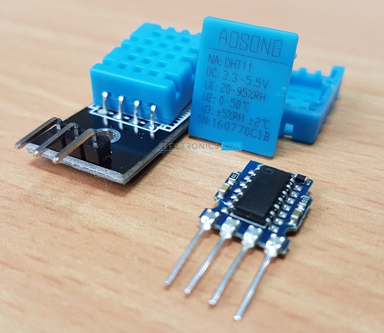
The DHT11 and its big brother DHT22 are cheap but highly reliable Humidity and Temperature Sensors. The range and accuracy of DHT22 is slightly better than that of DHT11, but this extended range and tighter accuracy comes at a price. Other than that, both the sensors are quire similar looking, with same pin out and connectivity. So, from now on, we will focus on the Sensor of this project i.e. the DHT11.
It is an ultra-low-cost sensor that houses a resistive type humidity measuring component, an NTC type temperature measuring component and an 8-bit Microcontroller to convert the data from both the measuring components to digital values.
In the Arduino – DHT11 tutorial, I have spoken a great deal about the working of the sensor as well as how to interpret data coming from its single line. I request you to refer to that project for additional information on this sensor.
Also, in that project, I haven’t used any dedicated libraries for the DHT11 Humidity and Temperature Sensor and tried out my own code. Just for a change, I will be using the DHT library developed by Adafruit.
Interfacing DHT11 Humidity and Temperature Sensor with STM32F103C8T6
Before proceeding further, I have to remind you something from the datasheet of the DHT11 Sensor. It says that the single data line between the DHT11 Sensor and the Microcontroller i.e. STM32 in this case, must be pulled HIGH with the help of a 5KΩ Resistor.
So, when shopping for DHT11 Sensor, try to buy module which includes the said pull-up resistor (and even some power-on LED). This makes it easier for Interfacing DHT11 Humidity and Temperature Sensor with STM32F103C8T6 as you don’t need any additional components.
The other thing to remember is that I have used an I2C LCD i.e. PCF8574 Module based I2C GPIO Expander Module with good old 16×2 LCD Display. I have already implemented the same in a dedicated project “Interfacing I2C LCD with STM32F103C8T6”. Refer to that project for additional information.
Components Required
- STM32F103C8T6 MCU based STM32 Blue Pill Board
- DHT11 Humidity and Temperature Sensor
- 16×2 LCD Display
- PCF8574 I2C LCD Module
- 5KΩ Resistor (Optional, no required if it is present on DHT11 Module)
- Connecting Wires
- USB to UART Converter (needed only if programming through UART)
Circuit Diagram
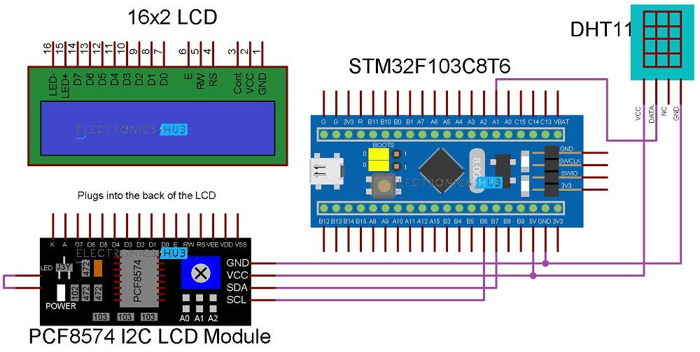
The following image shows the circuit diagram for Interfacing DHT11 Humidity and Temperature Sensor with STM32F103C8T6 MCU based STM32 Blue Pill Board.
Connections Explained
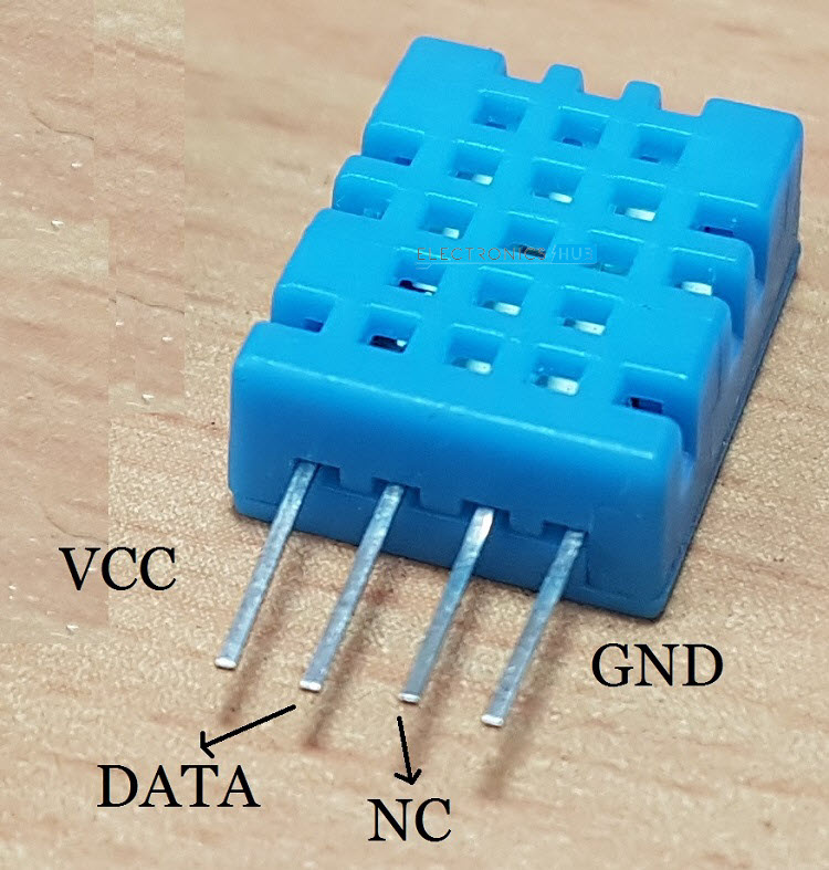
First, connect the VCC and GND pins of DHT11 Sensor to +5V and GND respectively. Then connect the Data pin of the sensor to pin PA1 of the STM32 board.
Coming to the LCD, plug-in the PCF8574 I2C LCD Module to the back of the LCD and connect the SDA and SCL pins of the PCF8574 Module to PB7 and PB6 pins of STM32 board respectively. Also, connect the VCC and GND pins of the I2C LCD Module to +5V and GND.
Programming STM32 for Interfacing DHT11
Before proceeding, make sure that you have figured out the slave address of the PCF8574 Module as mentioned in the I2C LCD Tutorial. You can use the following code for the same.
#include <Wire.h>
void setup()
{
Wire.begin();
Serial.begin(9600);
while (!Serial);
}
void loop()
{
byte error, address;
int I2CDevices;
Serial.println(“Scanning for I2C Devices…”);
I2CDevices = 0;
for (address = 1; address < 127; address++ )
{
Wire.beginTransmission(address);
error = Wire.endTransmission();
if (error == 0)
{
Serial.print(“I2C device found at address 0x”);
if (address < 16)
Serial.print(“0″);
Serial.print(address, HEX);
Serial.println(” !”);
I2CDevices++;
}
else if (error == 4)
{
Serial.print(“Unknown error at address 0x”);
if (address < 16)
Serial.print(“0”);
Serial.println(address, HEX);
}
}
if (I2CDevices == 0)
Serial.println(“No I2C devices found\n”);
else
Serial.println(“****\n”);
delay(5000);
}
Now, coming to the actual program, first download the DHT library from this link. Extract the zip file and copy the contents to the libraries folder of your local Arduino installation. This path will be usually “C:\Program Files (x86)\Arduino\libraries”.
Then, in the program, define the Data Pin of the DHT as PA1 and the type of DHT Sensor i.e. DHT11 or DHT22. Declare the I2C LCD with the LiquidCrystal_I2C library function by mentioning the slave address, number of columns and rows. You can now initialize both the LCD and the DHT11 Sensor with respective “begin” functions.
Now, take two float values and capture the Humidity as well as the Temperature readings from the sensor. Finally, print these values on the LCD.
Code
#include <Wire.h>
#include <LiquidCrystal_I2C.h>
#include <DHT.h>
#define DHTPIN PA1
#define DHTTYPE DHT11
LiquidCrystal_I2C lcd(0x27, 16, 2);
DHT dht(DHTPIN, DHTTYPE);
byte degree_symbol[8] =
{
0b00111,
0b00101,
0b00111,
0b00000,
0b00000,
0b00000,
0b00000,
0b00000
};
void setup()
{
lcd.begin();
dht.begin();
lcd.backlight();
lcd.setCursor(0,0);
lcd.print(“Electronics Hub”);
lcd.setCursor(0,1);
lcd.print(“DHT11 with STM32”);
delay(2000);
lcd.clear();
lcd.setCursor(0,0);
lcd.print(“Temp = “);
lcd.setCursor(0,1);
lcd.print(“Humid = “);
lcd.createChar(0, degree_symbol);
lcd.setCursor(12,0);
lcd.write(0);
lcd.print(“C”);
lcd.setCursor(14,1);
lcd.print(“%”);
}
void loop()
{
float hum = dht.readHumidity();
float tem = dht.readTemperature();
lcd.setCursor(7,0);
lcd.print(tem);
lcd.setCursor(8,1);
lcd.print(hum);
}
Conclusion
A simple project to demonstrate the Interfacing of DHT11 Humidity and Temperature Sensor with STM32F103C8T6 MCU based STM32 Blue Pill Board is implemented here.
