In this project, we will learn how to Interface 16×2 LCD with STMF103C8T6, which is otherwise known as the Blue Pill. I will show you how to connect a 16X2 Character LCD with STM32, some basic information about the LCD Module and write a program to print stuff on the LCD. So, let’s get started.
Introduction
In any embedded project, displaying important stuff on a display unit is very important as it gives the user an easy way to interact with the system. Take your energy meters, weather stations, heart rate monitoring systems and many more. All these projects have a display unit in their final implementation.
When talking about displays, it doesn’t have to be a fancy, colourful, graphical display. A simple character display is more than sufficient for displaying important stuff like readings from a sensor, the value of the ADC, status of a relay etc.
So, in this project, we will do the same. We will interface a 16X2 LCD with STM32F103C8T6 Blue Pill board. Since this is a demo for interfacing the LCD module, we will display some sample text just to see the output.
In the later projects when we will interface different sensors with STM32 Blue Pill, we can make use of this knowledge of 16X2 LCD with STM32F103C8T6 and display some important data.
A Brief note of 16X2 LCD
We have already used the 16X2 LCD display with many different Microcontrollers like 8051, ATmega, Arduino, LPC2148 (ARM7). But as a refresher, let us quickly have a brief intro of the same.
The following image shows a typical 16X2 Alphanumeric Character LCD Display. The term 16X2 means that it has 16 columns and 2 rows. Each column in a row is used to display a character and hence, in a 16X2 LCD display, you can display a maximum of 32 Characters at a time.
There are other flavours of these displays like 8X1, 8X2, 16X1, 16X2, 20X4, etc. but the most commonly used modules are the 16X2 and 20X4 displays.
Each column or character block is intern made up of 5*8 pixels (5 vertical and 8 horizontal). This essentially makes it a dot matrix display and to control the pixels, a very famous LCD Controller IC called the HD44780 from Hitachi is used.
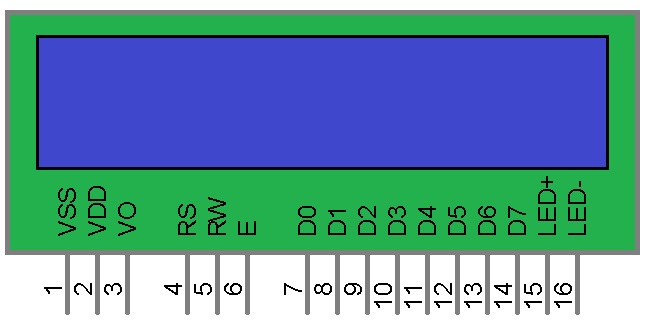
Coming to the pins of the 16*2 LCD display, it has 16 pins and the following table shows a quick description of those pins.
1 GND 2 +5V 3 Adjust contrast of LCD 4 Register Select (Command / Data) 5 Read / Write operations 6 Enable (must be HIGH for R / W) 7 – 14 Data Pins 15 LED Backlight Positive Supply (+5V) 16 LED Backlight Negative Supply (GND)
Pin Number
Pin Name
Description
VSS
VDD
VO
RS
R/W
EN
D0 – D7
LED+ (A)
LED- (K)
Interfacing 16X2 LCD with STM32F103C8T6
As mentioned earlier, this project is about getting to know how to interface a 16X2 LCD with STM32 Blue Pill. We will be using the Arduino IDE to write the code and upload it to the MCU (using a USB to Serial Converter).
The LCD module will be configured in 4-Bit mode so that only 4 data pins are used to transmit the data that is to be displayed on the LCD.
Circuit Diagram
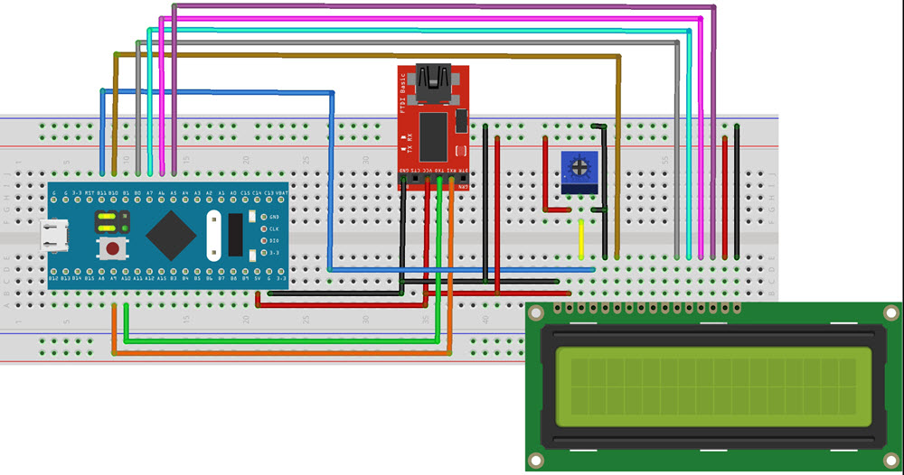
The following Fritzing image shows the circuit diagram for Interfacing 16X2 LCD with STM32F103C8T6 MCU.
Components Required
- STM32F103C8T6 MCU based board Blue Pill
- USB to Serial Converter (like FTDI Programmer)
- 16X2 Character LCD Module
- Connecting Wires
Connections
In the “Getting Started with STM32F103C8T6” tutorial, I have already explained the connections between the STM32 Blue Pill board and the USB to Serial Converter. The TX and RX of the FTDI Programmer are connected to A9 and A10 pins of the STM32 Blue Pill board.
Coming to the LCD Module, pins 1 and 2 i.e. VSS and VDD are connected to GND and +5V. Similarly, the pins 15 and 16 i.e. LED+ and LED- are connected to +5V and GND respectively.
To adjust the contrast of the LCD Display. The VO pin (Pin 3) is connected to the centre terminal of a 10KΩ POT, while the other two terminals of the POT are connected to +5V and GND. Coming to the control pins i.e. RS, RW and EN (Pins 4, 5 and 6), they are connected to B11, GND and B10 respectively.
Next are the data pins. We will be using the LCD in 4-bit mode so only 4 data pins i.e. D4 to D7 (Pins 11 to 14) are used. Connected these pins to B0, A7, A6 and A5 respectively. The other four data pins i.e. D0 to D3 can be left unused.
Programming STM32F103C8T6 for LCD Display
If you haven’t tried the “Getting Started with STM32F103C8T6” tutorial, then I suggest you to go through that project as I explain all the necessary information to work with STM32 Blue Pill and Arduino IDE in that tutorial.
Some important points you will need from that project are:
- Installing STM32 board packages for Arduino IDE.
- Selecting the right STM32 board with correct configurations.
- Downloading a programmer software that will work with Arduino IDE to upload the code to our Blue Pill board.
- Using BOOT Selection pins to switch between “Programming Mode” and “Operational Mode”.
If you have completed this basic setup and successfully uploaded a first program (Blinky), then you are good to go.
NOTE: You can switch between the Programming Mode and Operational Mode just by toggling the BOOT0 pins HIGH and LOW. If you are switching with power ON, then you have to press the Reset button every time you switch between the modes.
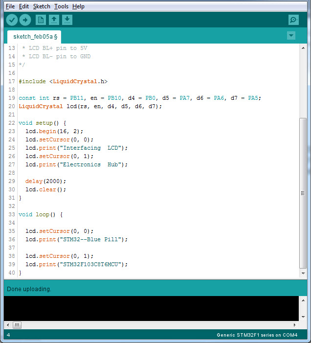
First, put the Blue Pill in Programming Mode by setting the BOOT0 pin to HIGH. Now, I have written a simple code using Arduino’s layout for displaying some text on the LCD display. The code is given below.
Code
/*
* LCD VSS pin to GND
* LCD VDD pin to 5V
* LCD VO pin to POT
* LCD RS pin to digital pin PB11
* LCD RW pin to GND
* LCD EN pin to digital pin PB10
* LCD D0 to D3 pins not used
* LCD D4 pin to digital pin PB0
* LCD D5 pin to digital pin PA7
* LCD D6 pin to digital pin PA6
* LCD D7 pin to digital pin PA5
* LCD BL+ pin to 5V
* LCD BL- pin to GND
*/
#include <LiquidCrystal.h>
const int rs = PB11, en = PB10, d4 = PB0, d5 = PA7, d6 = PA6, d7 = PA5;
LiquidCrystal lcd(rs, en, d4, d5, d6, d7);
void setup() {
lcd.begin(16, 2);
lcd.setCursor(0, 0);
lcd.print(“Interfacing LCD”);
lcd.setCursor(0, 1);
lcd.print(“Electronics Hub”);
delay(2000);
lcd.clear();
}
void loop() {
lcd.setCursor(0, 0);
lcd.print(“STM32–Blue Pill”);
lcd.setCursor(0, 1);
lcd.print(“STM32F103C8T6MCU”);
}
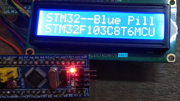
After compiling and uploading the code, the STM32 MCU will start displaying the text provided in the code. You can switch back to operational mode by making BOOT0 LOW and pressing the reset switch.
Conclusion
A simple project to learn How to Interface a 16X2 LCD with STM32 Blue Pill is implemented I tutorial. If we become familiar with the LCD interface, we can use the LCD Module in many of the future projects with ease.
