In this tutorial, I will show you how to interface an I2C LCD with STM32F103C8T6 MCU based STM32 Blue Pill Board. If you remember the “Interfacing 16X2 LCD with STM32F103C8T6” tutorial, I have already show you how simple it is to connect the LCD with STM32 and display some information. This project will be interesting as I will make use of I2C Communication to communicate with 16×2 LCD.
Introduction
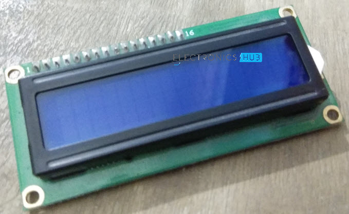
Small Alpha-Numeric Character Displays like the very popular 16×2 LCD Display are very useful little components as you can use them to display some important information related to your project. The information displayed on the LCD can be related to the project itself like a reading from a Temperature Sensor or special data like debug messages or error codes.
I have used 16×2 LCD display module in quite a lot of my projects with a wide variety of Microcontrollers like 8051, ARM7 based LPC2148, ATmega8, Arduino UNO and PIC.
This is all well and good but a small problem with 16×2 LCD or even the larger 20×4 LCD Display is it takes a lot of pins for interfacing with Microcontroller. Even in 4-bit data mode, the LCD needs atleast 6 Pins of the Microcontroller (four for the Data Pins, one for Register Select pin and one for Enable Pin, assuming the operation is Write i.e. R/W is connected to GND).
Using six pins of the Microcontroller to connect to a character display seems not that important but if your project is quite complex, then every pin of the MCU seems very important.
How to Interface I2C LCD with STM32F103C8T6?
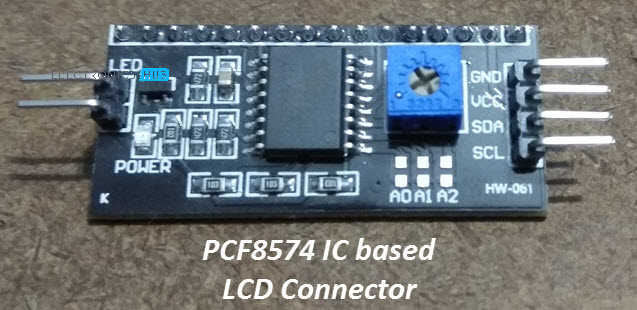
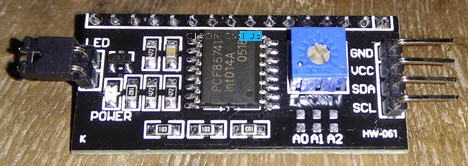
Here comes the PCF8574 GPIO Expander IC to the rescue. It comes as a dedicated module for interfacing 16×2 LCD Display with all the bells and whistles i.e. 10KΩ POT for Contrast adjustment of LCD, Pull-up resistors for I2C Communication, I2C Pins for connecting with Microcontroller etc.
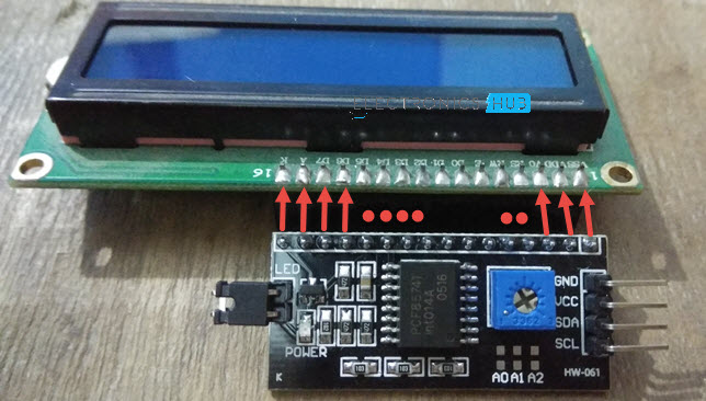
You can simply attach this module at the back of the 16×6 LCD Display and connect the I2C Pins to corresponding I2C Pins of the STM32 Blue Pill Board. It is that simple.
PCF8574 Module
I have already discussed about PCF8574 GPIO Expander IC in this “Interfacing PCF8574 with Arduino” tutorial. So, I will not go into the details but just a brief overview.
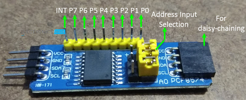
The PCF8574 is a 16 pin IC that acts as an I2C to 8-bit Parallel IO expander. What this means that using I2C Communication from Microcontroller, you can effectively increase the number of IO pins of your Microcontroller by 8.
An important thing to remember when buying a PCF8574 Module is that there are two type of them available in the market. One is a generic IO Expander Module, which can be used as, well an IO expander.
The other type of module is also based on the PCF8574 IC but it is designed in such a way that it can be used only with LCD Display i.e. 16×2 and even 20×4 LCDs. So, for this project, you have to choose the latter as it has all the necessary components and connections related to interfacing a 16X2 LCD Display.
Components Required
- STM32F103C8T6 MCU based STM32 Blue Pill Board
- PCF8574 IC based LCD Connector Module
- 16×2 LCD Display
- Connecting Wires
- USB to UART Converter Module (if programming through UART)
Circuit Diagram
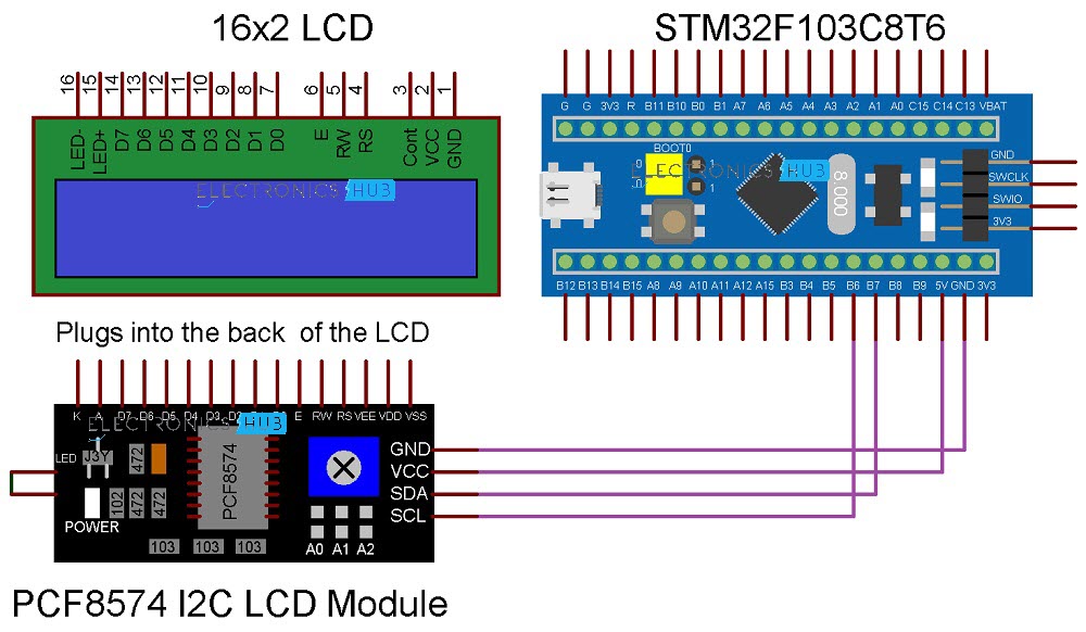
The following image shows the circuit diagram of Interfacing I2C with STM32F103C8T6 MCU based STM32 Blue Pill board.
Connections Explained
The connections for this project are very simple. Just plug-in the PCF8574 Module to the back of the 16×2 LCD. Check the pins of both the LCD and the PCF8574 Module before connecting. If connected correctly, the I2C pins on the PCF8574 Module will be easily accessible at the right of the display.
Now, connect the SDA pin of the PCF8574 Module to PB7 of STM32 and connect the SCL pin of the module to PB6 of STM32. Connect the VCC and GND pins of the PCF8574 Module to 5V and GND. This completes the necessary connections.
Identifying the Slave Address of PCF8574 Module
Before programming STM32 for Interfacing I2C LCD Display, we need to calculate the slave address of the PCF8574 Module. Since, Slave Address in I2C Communication is very important, you have to know it beforehand.
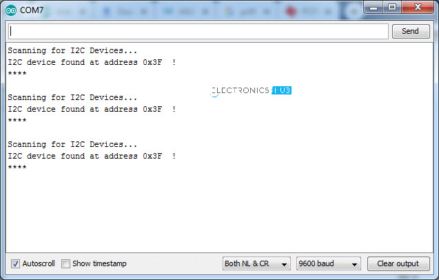
You can calculate the slave address by referring to the data sheet of PCF8574 IC and also the schematic of the PCF8574 I2C LCD Module. If you think it is a tedious process, then do not worry. There is another way to calculate the slave address by using the following code. This code will calculate the Slave Address and display it on the Serial Monitor.
Code
#include <Wire.h>
void setup()
{
Wire.begin();
Serial.begin(9600);
while (!Serial);
}
void loop()
{
byte error, address;
int I2CDevices;
Serial.println(“Scanning for I2C Devices…”);
I2CDevices = 0;
for (address = 1; address < 127; address++ )
{
Wire.beginTransmission(address);
error = Wire.endTransmission();
if (error == 0)
{
Serial.print(“I2C device found at address 0x”);
if (address < 16)
Serial.print(“0″);
Serial.print(address, HEX);
Serial.println(” !”);
I2CDevices++;
}
else if (error == 4)
{
Serial.print(“Unknown error at address 0x”);
if (address < 16)
Serial.print(“0”);
Serial.println(address, HEX);
}
}
if (I2CDevices == 0)
Serial.println(“No I2C devices found\n”);
else
Serial.println(“****\n”);
delay(5000);
}
In my case, the slave address is 0X3F. So, I have to use this Slave Address in the actual Program for STM32.
Programming STM32 for I2C LCD Display
After interfacing I2C LCD with STM32F103C8T6 MCU, we are now ready to write the program. There is a special library called “LiquidCrystal_I2C” developed for this module. You can download this library from this link. Extract the contents of the downloaded zip fie and place them in the libraries folder of your local Arduino installation.
Use the slave address that we got from the previous code and initialize the LCD Module with the same. Also specify the number of characters per row and number of rows of the LCD i.e. 16 and 2.
Using the “print” function of the library, you can display the characters you want on the LCD.
Code
#include <Wire.h>
#include <LiquidCrystal_I2C.h>
// Set the LCD address to 0x3F for a 16 chars and 2 line display
LiquidCrystal_I2C lcd(0x3F, 16, 2);
void setup()
{
lcd.begin();
lcd.backlight();
lcd.setCursor(0,0);
lcd.print(” I2C LCD with “);
lcd.setCursor(0,1);
lcd.print(” STM32F103C8T6 “);
}
void loop()
{
// Do nothing here…
}
Conclusion
A simple project for demonstrating how to interface I2C LCD with STM32F103C8T6 MCU based Blue Pill Board is implemented here.

One Response
Thank you, I’m starting to program and your demonstration was very useful for me