In this tutorial, I will show you how to use the PWM in STM32F103C8T6 MCU based STM32 Blue Pill Board. Using Pulse Width Modulation (PWM) in STM32 MCU, we will be controlling the speed of a small 5V DC Fan. You can also control the brightness of an LED using PWM technique.
Introduction
We have seen many PWM related projects here. We know that all microcontrollers work on digital domain and accessing or producing analog signal is not directly possible. PWM, which is short for Pulse Width Modulation, is a technique to produce analog signal using digital means.
This is done by making a digital Output pin HIGH and LOW at a certain frequency to produce a square wave. But this pure square wave is of no use. In order to make use of the digital controls, we can vary the HIGH time and LOW time of the square ware wave with in the fixed time period.
By varying the width of the ON and OFF period of the square wave, we can simulate voltages between full OFF (0 V) and full ON (5 V or 3.3 V). The duration of the ON time of the pulse is called the Width of the Pulse or simply Pulse Width. Since we are changing or “Modulating” this width, the technique is called as Pulse Width Modulation.
The ratio of the ON time to the total Time Period of a single Pulse is known as the Duty Cycle of the PWM Signal.
Duty Cycle = ON Time / (ON Time + OFF Time)
For a 50% duty cycle signal, both the ON time and the OFF time are equal. Hence, the output is a perfect square wave with an average voltage level of 2.5 V (if VDD is 5V). If we increase the duty cycle to 100%, then ON duration is maximum (i.e. the ON pulse occupies the whole length of the pulse). As a result, full 5V is produced by the signal.
By controlling the duty cycle, we can generate a precise voltage levels at the output of the PWM signal, which then can be used to control the speed of a Motor or adjust the brightness of an LED over fix the position of a Servo Motor, and many other things.
PWM in STM32F103C8T6
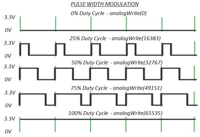
If you remember the “Getting Started with STM32F103C8T6” tutorial, I have pointed out that the STM32 Blue Pill board has 15 Pins capable of generating PWM Signals. The resolution of the PWM in STM32F103C8T6 is of 16-bit i.e. the maximum counter value is 216, which is equal to 65535.
So, if the counter value is set to 65535, we can achieve 100% duty cycle. If an LED and a DC Fan are connected, then the brightness of the LED is maximum, so is the speed of the fan.
For 50% duty cycle, the counter value must be set to 32767. This will result in half the maximum brightness and half the maximum speed.
The following image shows the PWM Signal for various Duty Cycles and corresponding values of the counter that must be written in the analogWrite function of Arduino.
Components Required
In this simple demonstration of PWM in STM32F103C8T6 MCU, I will be controlling the speed of a simple DC Fan and also the brightness of an LED. So, the complete list of the components required for this project are mentioned below.
- STM32F103C8T6 MCU based STM32 Blue Pill
- 5V DC Motor
- LED
- 10KΩ Potentiometer
- 220Ω Resistor
- ULN2003
- Connecting wires
- USB to UART Converter (if programming through UART)
- 16×2 LCD Display (Optional)
- 10KΩ Potentiometer (Optional)
Circuit Diagram
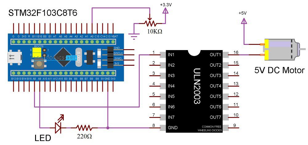
The following image shows the circuit diagram of the project.
Connections Explained
Since, we need to control the speed of a DC Motor, which is a high current device, we should not connect the Motor directly to the STM32 MCU but rather, through a Motor Driver. You can use dedicated Motor Driver IC like L293D or L298N but we can work with ULN2003 IC, which is a Darlington Array IC.
The limitation of driving a Motor using ULN2003 IC is that you cannot reverse the direction of rotation of the Motor. Pins 1 through 7 are Inputs (IN1 through IN7) while Pins 10 through 16 are Outputs (OUT7 through OUT1).
Since we are controlling only a single motor, the negative terminal of the motor is connected to the OUT1 Pin while the IN1 Pin is connected to a PWM Pin PA8. The positive end of the motor is connected to an external 5V power supply.
Coming to the LED, the anode of the LED is connected to another PWM Pin PA9 while the cathode is connected to GND through a Series 220Ω resistor.
To vary the input analog voltage, which in turn is converted to PWM Signal, a 10KΩ POT is connected to the ADC Pin PA0. The other two terminals of the POT are connected to 3.3V and GND.
You can use a 16×2 LCD Display to display the values of the ADC and Duty Cycle Value. I have not implemented this but if have followed my Interfacing 16×2 LCD with STM32F103C8T6 tutorial, then you can easily implement this.
Programming STM32 Blue Pill for PWM
First, the pins PA0, PA8 and PA9 are assigned to POT, Motor PWM and LED PWM respectively. Initialize the pins as INPUTS and OUTPUTS based on their function i.e. POT pin is INPUT while both the Motor Pin and the LED Pin are OUTPUTS.
Now, read the value of the Potentiometer using the ADC function analogRead. Store this value in a variable. Now using another variable, map the range of ADC i.e. 0 to 4095 to PWM Duty Cycle Range i.e. 0 to 65535. This will ensure that we get full range of voltages on the PWM Signals.
Using analogWrite function, generate the PWM Signals with the mapped value as the duty cycle value to both the LED and the Motor.
Code
const int potPIN = PA0;
const int ledPIN = PA9;
const int motorPIN = PA8;
void setup()
{
pinMode(potPIN, INPUT);
pinMode(ledPIN, OUTPUT);
pinMode(motorPIN, OUTPUT);
}
void loop()
{
int adcValue = analogRead(potPIN);
int dutyCycle = map(adcValue, 0, 4095, 0, 65535);
analogWrite(ledPIN, dutyCycle);
analogWrite(motorPIN, dutyCycle);
}
Conclusion
A simple demonstration on how to use Pulse Width Modulation or PWM in STM32F103C8T6 MCU based STM32 Blue Pill Board.
