In this tutorial, I will discuss one of the important concepts of a Microcontroller, the Interrupts. Also, I will show you how to use interrupts in STM32F103C8T6 Blue Pill Board. Using this knowledge on STM32 Interrupts, you can implement a better code for efficient use of the MCU.
Introduction
The Interrupt System is probably one of the important features in any MCU. STM32F103C8T6 is no exception. Interrupt in a Microcontroller is a hardware mechanism of informing the processor to stop the execution of current instruction and execute a special set of instructions, usually of higher priority.
In the Arduino Interrupts Tutorial, I have discussed a great deal about interrupts, polling and other related topics. I suggest you to read that tutorial before proceeding further as the general explanation of interrupts is more or less the same for all microcontrollers.
The main difference will be the actual hardware implementation of interrupts inside the microcontroller. I will talk about interrupts in STM32F103C8T6 in the next section.
Coming to this project, I will implement a simple circuit for demonstrating interrupts in STM32F103C8T6 Blue Pill Board by interfacing a button to the MCU and triggering an external interrupt to the MCU.
Interrupt Types and ISR
Basically, interrupts are classified into two types. They are:
- Hardware Interrupts
- Software Interrupts
Hardware Interrupts
Any interrupt which comes form a source that is external to the processor core is known as Hardware Interrupt. The simplest example is the Interrupt from an external button.
Software Interrupts
In case there is a problem with the program running on the MCU, then a Software Interrupt will be generated.
Interrupt Service Routine or Interrupt Handler
When ever an interrupt occurs, the corresponding Interrupt Service Routine (ISR) and in ARM terminology, an Interrupt Handler is invoked. In the event of an interrupt, the execution of current instruction is temporarily put to halt and the instructions in the Interrupt Handler is executed. After completion, the execution returns back to the halted instructions.
There are two important things to note about Interrupt Service Routines. The first thing is that instructions in the ISR must be as minimum as possible. The second thing is that you cannot use blocking functions like delay () in ISR.
Interrupts in STM32F103C8T6
In STM32 Blue Pill or the STM32F103C8T6 MCU to be specific, there is a special hardware unit called NVIC (short for Nested Vectored Interrupt Controller), which is responsible for managing all the external interrupts and peripheral interrupts.
If you remember Arduino’s External Interrupts, it has only two external interrupts i.e. INT0 and INT1 on digital IO pins 2 and 3. But in case of STM32F103C8T6, you can have up to 16 external interrupts on any GPIO pins. All you have to do is select the right pin in the program as per your circuit design.
How to Enable Interrupts in STM32F103C8T6?
Since we are developing the STM32 Blue Pill Applications using Arduino IDE, we can use the same syntax to configure external interrupts on STM32F103C8T6. This is done by a special function called “attachInterrupt ()” and its syntax is given below:
As you can see from the above syntax, the attachInterrupt () function takes three arguments. They are:
- digitalPinToInterrupt(pin)
- ISR
- Mode
In the first argument digitalPinToInterrupt(pin), you have to mention the Pin of the MCU from which an external Interrupt is expected. For example, if a button is connected to PA0, then the argument will be “digitalPinToInterrupt(PA0)”.
The second argument is name of the Interrupt Handler or the Interrupt Service Routine (ISR) function. The function must have a void return type and should not take any arguments.
Finally, the third argument in the attachInterrupt () function is to specify mode of triggering the interrupt i.e. at what point of signal transition, the interrupts must be triggered. Usually, in Arduino environment, this argument can have any one of the five predefined constants but in case of STM32, you have options for choosing one from the following three values.
- CHANGE: Trigger the Interrupt when there is a change in the pin value.
- RISING: Trigger the Interrupt when the pin value rises from LOW to HIGH.
- FALLING: Trigger the Interrupt when the pin value falls from HIGH to LOW.
Circuit Diagram
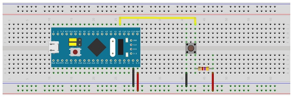
Now that we have seen a little bit about interrupts in STM32F103C8T6 MCU, let us proceed with the demonstration of the project. The following image represents a simple circuit diagram for interfacing a button with STM32 MCU and triggering an interrupt.
Components Required
- STM32F103C8T6 Blue Pill Board
- Push Button
- USB to UART Converter (if programming via UART)
- Connecting Wires
- USB Cable
Programming STM32 Blue Pill for Button Interrupt
First, the Button is connected to Pin PA0. Also, the pin is PA0 is pulled HIGH with the help of a 4.7KΩ resistor. The other end of the button is connected to GND.
The following code is used to activate interrupt on pin PA0 and the button_ISR will help in toggling the LED.
int ledPin = PC13;
int buttonPin = PA0;
int ledToggle;
int previousState = HIGH;
unsigned int previousPress = 0;
volatile int buttonFlag;
int buttonDebounce = 20;
void setup()
{
pinMode(ledPin, OUTPUT);
pinMode(buttonPin, INPUT);
attachInterrupt(digitalPinToInterrupt(buttonPin), button_ISR, CHANGE);
}
void loop()
{
if((millis() – previousPress) > buttonDebounce && buttonFlag)
{
previousPress = millis();
if(digitalRead(buttonPin) == LOW && previousState == HIGH)
{
ledToggle =! ledToggle;
digitalWrite(ledPin, ledToggle);
previousState = LOW;
}
else if(digitalRead(buttonPin) == HIGH && previousState == LOW)
{
previousState = HIGH;
}
buttonFlag = 0;
}
}
void button_ISR()
{
buttonFlag = 1;
}
Conclusion
A simple project to demonstrate the working of External Interrupts in STM32F103C8T6 Blue Pill is implemented here. When the button is pressed, an interrupt is triggered and the STM32 MCU will execute the simple ISR and returns to toggle the state of the LED.

One Response
Would be very interesting if you explaim what happens whem 2 interrupt appear at the same time